Quantcast
Channel: Severalnines
Viewing all 1476 articles
Browse latest View live

MariaDB Cluster Offline Installation for CentOS

$
0
0

Most of the installation steps available on the Internet cover the standard online installation, presuming the database hosts are having an active internet connection to the package repositories and satisfy all dependencies. However, installation steps and commands are a bit different for offline installation. Offline installation is a common practice in a strict and secure environment like financial and military sectors for security compliance, reducing the exposure risks and maintaining confidentiality. 

In this blog post, we are going to install a three-node MariaDB Cluster in an offline environment on CentOS hosts. Consider the following three nodes for this installation:

  • mariadb1 - 192.168.0.241
  • mariadb2 - 192.168.0.242
  • mariadb3 - 192.168.0.243

Download Packages

The most time-consuming part is getting all the packages required for our installation. Firstly, go to the respective MariaDB repository that we want to install (in this example, our OS is CentOS 7 64bit):

Make sure you download the exact same minor version for all MariaDB-related packages. In this example, we downloaded MariaDB version 10.4.3. There are a bunch of packages in this repository but we don't need them all just to run a MariaDB Cluster. Some of the packages are outdated and for debugging purposes. For MariaDB Galera 10.4 and CentOS 7, we need to download the following packages from the MariaDB 10.4 repository:

  • jemalloc
  • galera-3
  • libzstd
  • MariaDB backup
  • MariaDB server
  • MariaDB client
  • MariaDB shared
  • MariaDB common
  • MariaDB compat

The following wget commands would simplify the download process:

wget http://yum.mariadb.org/10.4/centos8-amd64/rpms/galera-4-26.4.4-1.rhel8.0.el8.x86_64.rpm 
wget http://yum.mariadb.org/10.4/centos8-amd64/rpms/MariaDB-backup-10.4.13-1.el8.x86_64.rpm
wget http://yum.mariadb.org/10.4/centos8-amd64/rpms/MariaDB-client-10.4.13-1.el8.x86_64.rpm
wget http://yum.mariadb.org/10.4/centos8-amd64/rpms/MariaDB-common-10.4.13-1.el8.x86_64.rpm
wget http://yum.mariadb.org/10.4/centos8-amd64/rpms/MariaDB-compat-10.4.13-1.el8.x86_64.rpm
wget http://yum.mariadb.org/10.4/centos8-amd64/rpms/MariaDB-server-10.4.13-1.el8.x86_64.rpm
wget http://yum.mariadb.org/10.4/centos8-amd64/rpms/MariaDB-shared-10.4.13-1.el8.x86_64.rpm

Some of these packages have dependencies to other packages. To satisfy them all, it's probably best to mount the operating system ISO image and point the yum package manager to use the ISO image as an offline base repository instead. Otherwise, we would waste a lot of time trying to download/transfer the packages from one host/media to another.

If you are looking for older MariaDB packages, look them up in its archive repository here. Once downloaded, transfer the packages into all the database servers via USB drive, DVD burner or any network storage connected to the database hosts.

Mount the ISO Image Locally

Some of the dependencies are needed to be satisfied during the installation and one way to achieve this easily is by setting up the offline yum repository on the database servers. Firstly, we have to download the CentOS 7 DVD ISO image from the nearest CentOS mirror site, under "isos" directory:

$ wget http://centos.shinjiru.com/centos/7/isos/x86_64/CentOS-7-x86_64-DVD-2003.iso

You can either transfer the image and mount it directly or burn it into a DVD and use the DVD drive and connect it to the server. In this example, we are going to mount the ISO image as a DVD in the server:

$ mkdir -p /media/CentOS

$ mount -o loop /root/CentOS-7-x86_64-DVD-2003.iso /media/CentOS

Then, enable the CentOS-Media (c7-media) repository and disable the standard online repositories (base,updates,extras):

$ yum-config-manager --disable base,updates,extras

$ yum-config-manager --enable c7-media

We are now ready for the installation.

Installing and Configuring the MariaDB Server

Installation steps are pretty straightforward if we have all the necessary packages ready. Firstly, it's recommended to disable SElinux (or set it to permissive mode):

$ setenforce 0

$ sed -i 's/^SELINUX=.*/SELINUX=permissive/g' /etc/selinux/config

Navigate to the directory where all the packages are located, in this case, /root/installer/. Make sure all the packages are there:

$ cd /root/installer

$ ls -1

boost-program-options-1.53.0-28.el7.x86_64.rpm

galera-4-26.4.4-1.rhel7.el7.centos.x86_64.rpm

jemalloc-3.6.0-1.el7.x86_64.rpm

libzstd-1.3.4-1.el7.x86_64.rpm

MariaDB-backup-10.4.13-1.el7.centos.x86_64.rpm

MariaDB-client-10.4.13-1.el7.centos.x86_64.rpm

MariaDB-common-10.4.13-1.el7.centos.x86_64.rpm

MariaDB-compat-10.4.13-1.el7.centos.x86_64.rpm

MariaDB-server-10.4.13-1.el7.centos.x86_64.rpm

MariaDB-shared-10.4.13-1.el7.centos.x86_64.rpm

Let's install the mariabackup dependency called socat first and then run the yum localinstall command to install the RPM packages and satisfy all dependencies:

$ yum install socat

$ yum localinstall *.rpm

Start the MariaDB service and check the status:

$ systemctl start mariadb

$ systemctl status mariadb

Make sure you see no error in the process. Then, run the mysql_secure_installation script to configure the MySQL root password and hardening:

$ mysql_secure_installation

Make sure the MariaDB root password is identical on all MariaDB hosts. Create a MariaDB user to perform backup and SST. This is important if we want to use the recommended mariabackup as the SST method for MariaDB Cluster, and also for backup purposes:

$ mysql -uroot -p

MariaDB> CREATE USER backup_user@localhost IDENTIFIED BY 'P455w0rd';

MariaDB> GRANT SELECT, INSERT, CREATE, RELOAD, PROCESS, SUPER, LOCK TABLES, REPLICATION CLIENT, SHOW VIEW, EVENT, CREATE TABLESPACE ON *.* TO backup_user@localhost;

We need to modify the default configuration file to load up MariaDB Cluster functionalities. Open /etc/my.cnf.d/server.cnf and make sure the following lines exist for minimal configuration:

[mysqld]

log_error = /var/log/mysqld.log


[galera]

wsrep_on=ON

wsrep_provider=/usr/lib64/galera-4/libgalera_smm.so

wsrep_cluster_address=gcomm://192.168.0.241,192.168.0.242,192.168.0.243

binlog_format=row

default_storage_engine=InnoDB

innodb_autoinc_lock_mode=2

bind-address=0.0.0.0

innodb_flush_log_at_trx_commit=2

wsrep_sst_method=mariabackup

wsrep_sst_auth=backup_user:P455w0rd

wsrep_node_address=192.168.0.241 # change this

Don't forget to change the wsrep_node_address value with the IP address of the database node for MariaDB Cluster communication. Also, the wsrep_provider value might be different depending on the MariaDB server and MariaDB Cluster version that you have installed. Locate the libgalera_smm.so path and specify it accordingly here.

Repeat the same steps on all database nodes and we are now ready to start our cluster.

Bootstrapping the Cluster

Since this is a new cluster, we can pick any of the MariaDB nodes to become the reference node for the cluster bootstrapping process. Let's pick mariadb1. Make sure the MariaDB is stopped first, then run the galera_new_cluster command to bootstrap:

$ systemctl stop mariadb

$ galera_new_cluster

$ systemctl status mariadb

On the other two nodes (mariadb2 and mariadb3), we are going to start it up using standard MariaDB start command:

$ systemctl stop mariadb

$ systemctl start mariadb

Verify if all nodes are part of the cluster by looking at the wsrep-related status on every node:

MariaDB> SHOW STATUS LIKE 'wsrep%';

Make sure the reported status are as the following:

wsrep_local_state_comment     | Synced

wsrep_cluster_size            | 3

wsrep_cluster_status          | Primary

For MariaDB 10.4 and Galera Cluster 4, we can get the cluster member information directly from mysql.wsrep_cluster_members table on any MariaDB node:

$ mysql -uroot -p -e 'select * from mysql.wsrep_cluster_members'

Enter password:

+--------------------------------------+--------------------------------------+---------------+-----------------------+

| node_uuid                            | cluster_uuid                         | node_name     | node_incoming_address |

+--------------------------------------+--------------------------------------+---------------+-----------------------+

| 35177dae-a7f0-11ea-baa4-1e4604dc8f68 | de82efcb-a7a7-11ea-8273-b7a81016a75f | maria1.local  | AUTO                  |

| 3e6f9d0b-a7f0-11ea-a2e9-32f4a0481dd9 | de82efcb-a7a7-11ea-8273-b7a81016a75f | maria2.local  | AUTO                  |

| fd63108a-a7f1-11ea-b100-937c34421a67 | de82efcb-a7a7-11ea-8273-b7a81016a75f | maria3.local  | AUTO                  |

+--------------------------------------+--------------------------------------+---------------+-----------------------+

If something goes wrong during the cluster bootstrapping, check the MySQL error log at /var/log/mysqld.log on all MariaDB nodes. Once a cluster is bootstrapped and running, do not run galera_new_cluster script again to start a MariaDB service. It should be enough by using the standard "systemctl start/restart mariadb" command, unless there is no database node in PRIMARY state anymore. Check out this blog post, How to Bootstrap MySQL or MariaDB Cluster to understand why this step is critical.

Bonus Step

Now you already have a database cluster running without any monitoring and management features. Why don't you import the database cluster into ClusterControl? Install ClusterControl on another separate server, and setup passwordless SSH from the ClusterControl server to all database nodes. Supposed the ClusterControl server IP is 192.168.0.240, run the following commands on ClusterControl server:

$ whoami

root

$ ssh-keygen -t rsa # press Enter for all prompts

$ ssh-copy-id root@192.168.0.241 # root password on 192.168.0.241

$ ssh-copy-id root@192.168.0.242 # root password on 192.168.0.242

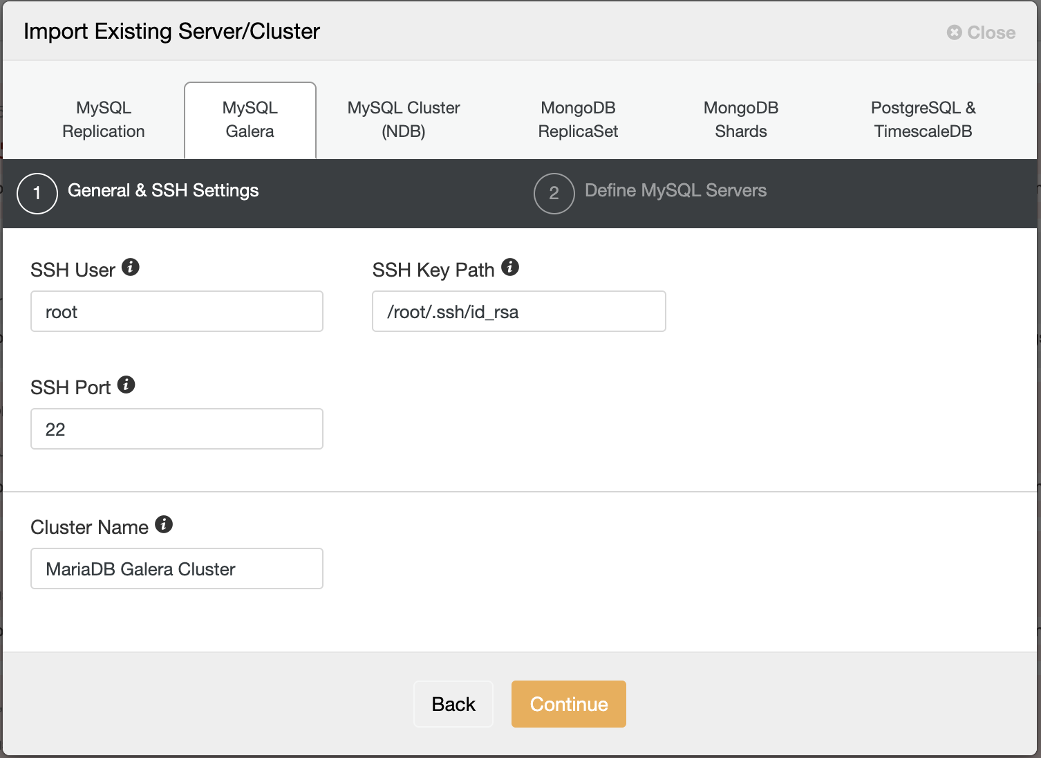
$ ssh-copy-id root@192.168.0.243 # root password on 192.168.0.243

Then go to ClusterControl -> Import -> MySQL Galera and enter the required SSH details:

Import MariaDB Cluster

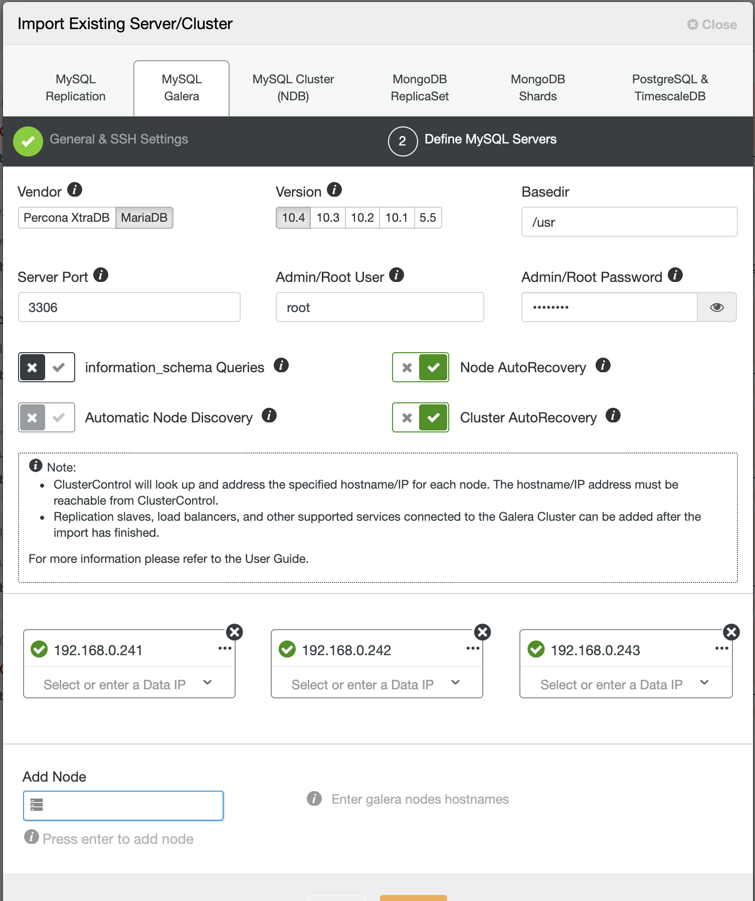
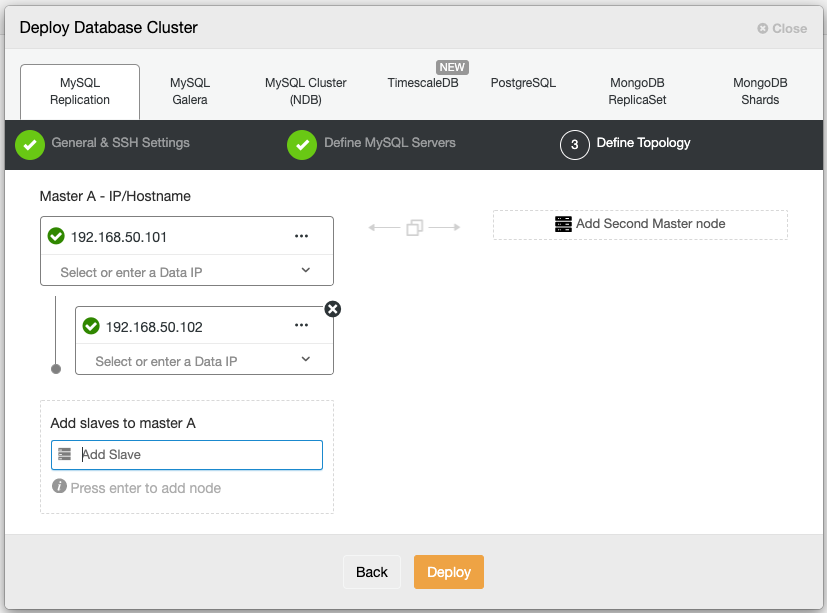
In the second step under Define MySQL Servers, toggle off "Automatic Node Discovery" and specify all the IP address of the database nodes, and make sure there is a tick green next to the IP address, indicating ClusterControl is able to reach the node via passwordless SSH:

Import MariaDB Cluster

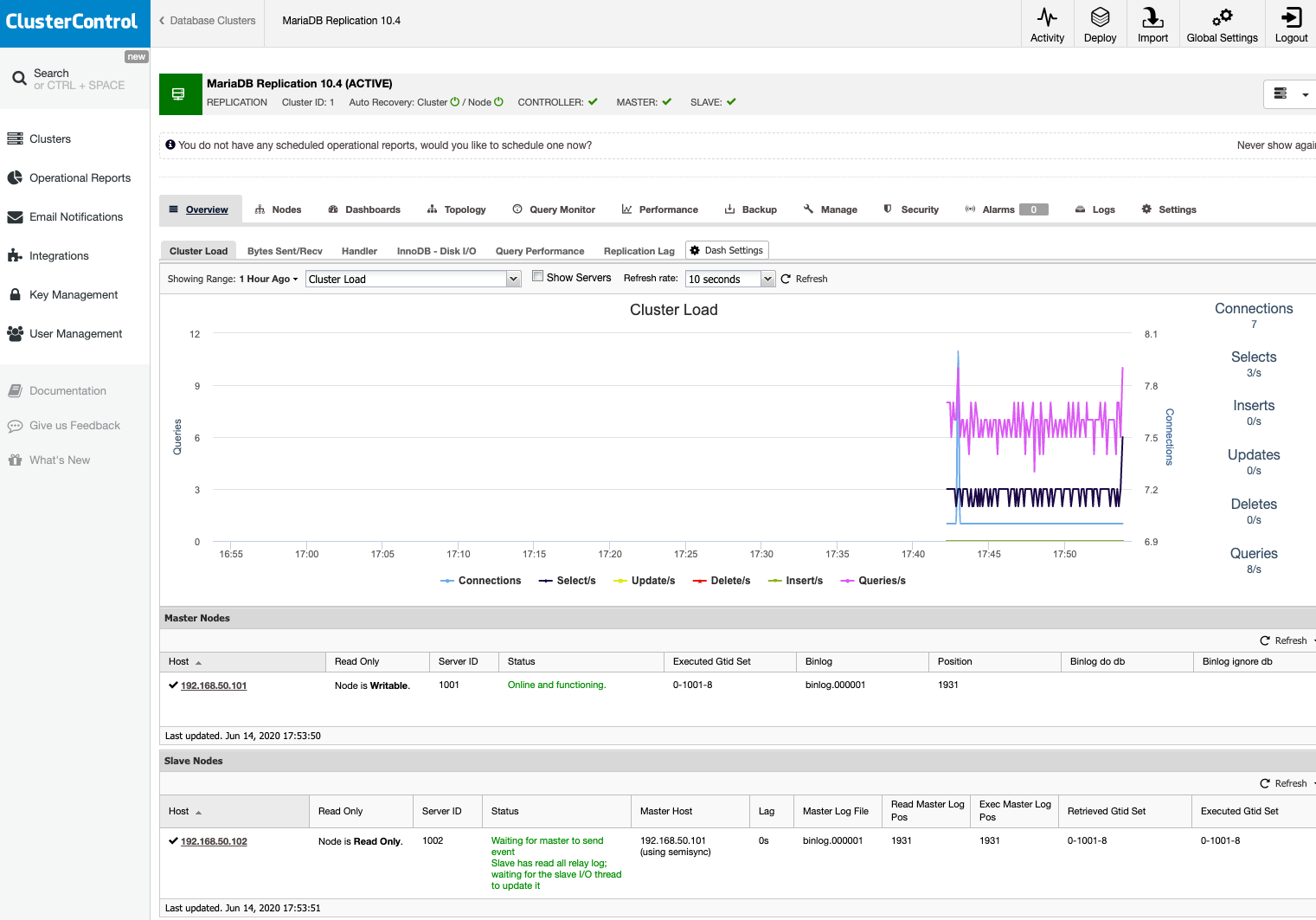
Click Import and wait until the import job completes. You should see it under the cluster list:

Import MariaDB Cluster

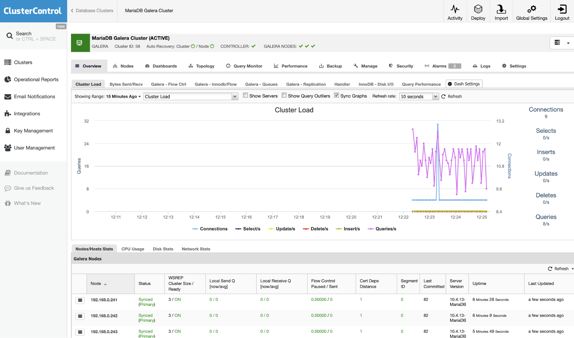
You are in good hands now. Note that ClusterControl will default to 30-day full enterprise features and after it expires, it will default back to Community Edition, which is free forever.


Eliminating PostgreSQL Split-Brain in Multi-Cloud Databases

$
0
0

Using a multi-cloud or multi-datacenter environment is useful for geo-distributed topologies or even for a disaster recovery plan, and actually, it is becoming more popular nowadays, therefore the concept of split-brain is also becoming more important as the risk of having it increase in this kind of scenario. You must prevent a split-brain to avoid potential data loss or data inconsistency, which could be a big problem for the business.

In this blog, we will see what a split-brain is, and how ClusterControl can help you to avoid this important issue.

What is Split-Brain?

In the PostgreSQL world, split-brain occurs when more than one primary node is available at the same time (without any third-party tool to have a multi-master environment) that allows the application to write in both nodes. In this case, you’ll have different information on each node, which generates data inconsistency in the cluster. Fixing this issue could be hard as you must merge data, something that sometimes is not possible.

PostgreSQL Split-Brain in a Multi-Cloud Topology

Let’s suppose you have the following multi-cloud topology for PostgreSQL (which is a pretty common topology nowadays):

PostgreSQL Split-Brain in a Multi-Cloud Topology

Of course, you can improve this environment by, for example, adding an Application Server in the Cloud Provider 2, but in this case, let’s use this basic configuration.

If your primary node is down, one of the standby nodes should be promoted as a new primary and you should change the IP address in your application to use this new primary node.

There are different ways to make this in an automatic way. For example, you can use a virtual IP address assigned to your primary node and monitor it. If it fails, promote one of the standby nodes and migrate the virtual IP address to this new primary node, so you don’t need to change anything in your application, and this can be made using your own script or tool.

At the moment, you don’t have any issue, but… if your old primary node comes back, you must make sure you won’t have two primary nodes in the same cluster at the same time.

The most common methods to avoid this situation are:

  • STONITH: Shoot The Other Node In The Head.
  • SMITH: Shoot Myself In The Head.

PostgreSQL doesn’t provide any way to automate this process. You must make it on your own.

How to Avoid Split-Brain in PostgreSQL with ClusterControl

Now, let’s see how ClusterControl can help you with this task.

First, you can use it to deploy or import your PostgreSQL Multi-Cloud environment in an easy way as you can see in this blog post.

Then, you can improve your topology by adding a Load Balancer (HAProxy), which you can also do using ClusterControl following this blog. So, you will have something like this:

How to Avoid Split-Brain in PostgreSQL with ClusterControl

ClusterControl has an auto-failover feature that detects master failures and promotes a standby node with the most current data as a new primary. It also fails over the rest of the standby nodes to replicate from the new primary node. 

HAProxy is configured by ClusterControl with two different ports by default, one read-write and one read-only. In the read-write port, you have your primary node as online and the rest of your nodes as offline, and in the read-only port, you have both the primary and the standby nodes online. In this way, you can balance the reading traffic between your nodes but you make sure that at the time of writing, the read-write port will be used, writing in the primary node that is the server that is online.

How to Avoid Split-Brain in PostgreSQL with ClusterControl

When HAProxy detects that one of your nodes, either primary or standby, is not accessible, it automatically marks it as offline and does not take it into account for sending traffic to it. This check is done by health check scripts that are configured by ClusterControl at the time of deployment. These check whether the instances are up, whether they are undergoing recovery, or are read-only. 

If your old primary node comes back, ClusterControl will also avoid starting it, to prevent a potential split-brain in case you have a direct connection that is not using the Load Balancer, but you can add it to the cluster as a standby node in an automatic or manual way using the ClusterControl UI or CLI, then you can promote it to have the same topology that you had running before the issue.

Conclusion

Having the “Autorecovery” option ON, ClusterControl will perform this automatic failover as well as notify you of the problem. In this way, your systems can recover in seconds without your intervention and you will avoid a split-brain in a PostgreSQL Multi-Cloud environment.

You can also improve your High Availability environment by adding more ClusterControl nodes using the CMON HA feature described in this blog.

How to Reduce Replication Lag in Multi-Cloud Deployments

$
0
0

Replication lag is an inevitable occurrence for multi-cloud database deployments, as it causes delays of transactions to reflect into the target node or cluster. When implementing a multi-cloud database deployment, the most common scenario (and the reason why organizations tend to implement this) for multi-cloud is to have a disaster response mechanism for your architectural and underlying environment. An outage with downtime can cost your business money, often costing more money than if the Disaster and Recovery Plan (DRP) was not addressed and not planned beforehand. 

Implementing a multi-cloud database should not be done without analyzing each of the components that comprises the entire stack. In this blog we'll address some of those issues, but will primarily look at data consistency issues brought out by replication lag common to multi-cloud deployments.

Multi-Cloud Deployments

A common setup for multi-cloud deployments is where clusters are situated not only in different regions, but also on different providers. Providers, however, often have different hardware configurations (Azure, Google Cloud, AWS) and data centers that run these compute nodes that run your application and databases. We have discussed this previously on what can be the common cases and reasons why certain organizations and companies embrace multi-cloud database setup.

A common deployment can look like the structure below,

Multi-Cloud Deployments

From applications (either running on containers), then connects to proxies, and proxies balance over through the database cluster or nodes depending on traffic demand. Interconnection between different cloud providers requires that it has to connect securely and the most common approach is over a VPN connection. Wireguard can be an option as well to establish a virtual connection between clouds. For production-based VPN's, a cloud VPN gateway is a great option. Not only does it provide high availability, it offers you with secure downtime, high service availability (with SLA), and bandwidth speed; especially when a high transfer rate is needed. When dealing with replication lag, there's no doubt you'll find this type of service helpful.

Other Ways to Reduce Lag in your Multi-Cloud Deployments

Reducing lag is a complex process. There are a ton of things to consider as to what could cause your replication between clouds to lag. Certain occasions, when replication lag tends to accumulate high, can then fix itself over a period of time. These are acceptable for some cases when a certain occurrence of execution or expected amount of traffic is bound to happen. 

Although certain formulas that work (and that you think are enough) may be ok in a traditional environment, but in a multi-cloud environment, there's a lot of things to consider and look at between cloud providers. However, in every problem, there can always be a solution but we'll go through the basics and vital areas to look upon.

Cloud Infrastructure

A difference between cloud infrastructure can impact lag. For example, the difference between the type of compute node specifications matters. The number of vCPus, CPUs, memory, storage, network bandwidth and hardware are things you need to know. Memory and CPU contention,  disk throughput, network latency, issues with concurrency, impacts your instance in the cloud. It also depends on what type of queries or transactions you are serving coming from your client, down to your database cluster. Then your database cluster replicates to the other cluster which resides in another cloud provider. If you're using general purpose instances, it might produce poor performance if you're serving tons of query requests or handling bulk updates to your tables and databases. Not only the queries are required to be handled, if you run onto specific or custom configurations of your databases, for example, using encryption such as TLS/SSL, it can be CPU bound and that might produce outstanding impact for general purpose type instances.

Running or hosting your database VM's on a multi-tenant hardware provides impact as well. You'll have to take note that there are compute nodes running as guest OS will run on that particular hosting hardware. If such a high-computing node runs on the same tenant, it can impact as well where your compute node is running. For example, disks may also run out of memory, I/O and CPU, keeping data from being written down to the storage can cause your replica to fall further behind the primary node in the other region or cloud. An alternative option which can be dealt with the cloud provider is to use dedicated instances or hosts. These are physically isolated at the hardware level, although there can be instances that it shares hardware with other instances from the same account that are not dedicated instances.

While those mentioned above help determine the source and impact of lag, reducing the lag is very important to know your underlying hardware and its sole purpose which is to replicate the data from one cluster within another cloud provider, to another cluster of a different provider. Instead of running database transactions to the receiving replica (the node which will intercept replicated data from the other cluster of a different cloud provider), you can dedicate the tasks and responsibility of node only for syncing and replicating your data and nothing else. Avoiding unwanted tasks aside from replication helps your replica node to catch up with the master as quick as possible. Distance matters also wherever your database clusters belong to. For example, if both clusters run on different regions, yet these regions are based on eastern-us vs asia-east, this can be a problem. It would make sense to use the same region or use the nearest region if the latter is not possible. If your mission is to expand your system using multi-cloud deployments for your mission critical systems and avoid downtime and outage, then lag and data drift is very important to be avoided.

For MySQL Lag within Intra-Cloud Deployments

A very common approach for replication with MySQL is using the single-threaded replication. This works all the time especially for a simple setup with low to moderately high demand replication. However, there are certain cases that replication lag on a master-slave setup can cause consistent and frequent issues. Hence, you do need your slave node to catch up with your master wherein both nodes reside on different cloud providers. A great deal to handle this is to use parallelism with replication. Using --slave-parallel-type=[DATABASE, LOGIAL_CLOCK] with a combination of binlog_group_commit_sync_delay helps drastically reduce the slave lag. 

Of course hardware can be your sweet spot here to address performance issues especially on a high-traffic systems, it might help boost as well if you relax some variables such as sync_binlog, innodb_flush_log_at_trx_commit, and innodb_flush_log_at_timeout

For Galera-based clusters, keeping up with clusters of different clouds can be a challenge as well. However, it's advisable to set your Galera clusters using different segments. You can do this by setting your gmcast.segment value for every cluster separated to a different region or cloud. 

For PostgreSQL within Intra-Cloud Deployments

A common approach for replication with PostgreSQL is to use physical streaming replication. It might depend on your desired setup but reducing a replication lag with streaming replication is a good deal here. Of course logical replication or using continuous archiving is an option but it may not be an ideal setup and exposes limited capability when dealing with monitoring and management especially with different cloud providers and also the major concern for reducing your replica lag when tuning and monitoring it. Unless you're using third-party extensions such as pglogical or BDR from 2ndQuadrant for your logical replication, but that's not covered here in the blog and it's out of scope for the main topic.

A good approach to deal with this is to dedicate your replication streams only for that purpose. For example, two replication streams (primary and standby) do not receive any read queries but only do replication streams alone. These two nodes which reside in different cloud providers must have secondary nodes in case one fails, so preserve a highly available environment especially for mission critical systems.

With physical streaming replication, you may take advantage of tuning the variables hot_standby_feedback = off and max_standby_streaming_delay longer than 0 in your postgresql.conf. Twitch uses 6h value on their setup but they might add changes since this post of their blog. Tuning these variables help avoid the replication source from not being burdened and replication will not cancel queries because of multi-version concurrency control (MVCC). 

Also when dealing with replication lag, you may consider checking your transaction isolation. For some cases, a specific transaction isolation might cause impact (e.g. using SERIALIZABLE) in your replicating node.

For MongoDB within Intra-Cloud Deployments

MongoDB addresses this in their manual on how to troubleshoot especially for replica sets. Common reasons are network latency, disk throughput, concurrency, and bulk changes or large data sent to your MongoDB replica. If your major business requires dealing with large data and you have a mission critical system, then investing for a dedicated instance or host can be your great deal of choice here. A common concern can be impacted if your compute instances are running on multi-tenant systems.

Concurrency can be a major concern with MongoDB especially large and long running write operations. This can cause your system to stop because the system is locked and incoming operations are blocked affecting replication to your replica situated on a different cloud provider, and this will increase replication lag. In the replica or secondary level, also, a common issue similar to concurrency, is when running frequent and large write operations. The disk of the replica will be unable to read the oplog resulting in a poor performance and can have hard time catching up with the primary and causing the replication to fall behind. Killing or terminating running operations is not an option here especially if you data has been written already from the primary cluster or primary node.

Lastly, as those concerns will not be mitigated until known. Avoiding writes to your replica or secondary nodes situated on the other cloud will help avoid concurrency and poor performance that can impact during replication. 

Monitoring Your Replication Lag

Using external tools available at your own disposal can be the key here. However, choosing the right tool for monitoring is the key here to understand and analyze how your data performs. ClusterControl which offers monitoring and management is a great deal to start from when deploying multi-cloud databases. For example, the screenshot below provides you a great deal to determine network performance, CPU utilization, flow control of your Galera-based cluster:

Monitoring Your Replication Lag

ClusterControl supports PostgreSQL/TimescaleDB, MongoDB, MySQL/MariaDB including Galera Clusterdeployments, management, and monitoring. It also offers query analysis on what queries are impacting your cluster and provides advisors to deal with the issues that are detected and provide you solutions to solve the problem. Expanding your cluster onto a different cloud provider is not that difficult with ClusterControl.

Conclusion

Different cloud providers have different infrastructure yet might offer solutions to help you mitigate lags to your database deployments. However, this might be difficult and goes complicated without proper monitoring tools regardless of your expertise and skills to know what can cause your database replication lag in your multi-cloud environment. A manual check is not a great idea when critical systems that require rapid response. It requires higher observability of your cluster. A rapid solution has to be in place before replication lag escalates to a higher degree of impact. So choose the right tool at your own expense and avoid drastic measures when a crisis hits.


Troubleshooting a MongoDB Sharded Cluster

$
0
0

In MongoDB, large data sets involve high throughput operations and this may overwhelm the capacity of a single server. Large working data sets implicate more stress on the I/O capacity of disk devices and may lead to a problem such as Page Faults.

There are mainly two ways of solving this...

  1. Vertical Scaling: increasing single server capacity. Achieved by adding more CPU, RAM and storage space but with a limitation that: available technology may restrict a single machine from being sufficiently powerful for some workload. Practically, there is a maximum for vertical scaling.
  2. Horizontal Scaling Through Sharding: This involves dividing system dataset over multiple servers hence reducing the overall workload for a single server. Expanding the capacity of the deployment only requires adding more servers to lower overall cost than high-end hardware for a single machine.  However, this comes with a trade off that there will be a lot of complexity in infrastructure and maintenance for the deployment. The complexity gets more sophisticated when troubleshooting the sharded cluster in an event of disaster. In this blog, we provide some of the troubleshooting possibilities that may help:
  3. Selecting Shard Keys and Cluster Availability 
  4. Mongos instance becoming unavailable
  5. A member becomes absent from the shard replica set
  6. All members of a replica set are absent
  7. Stale config data leads to Cursor Fails
  8. Config server becomes unavailable
  9. Fixing Database String Error
  10. Avoiding Downtime when moving config servers

Selecting Shard Keys and Cluster Availability

Sharding involves dividing data into small groups called shards so as to reduce the overall workload for a given throughput operation. This grouping is achieved through selecting an optimal key which is mainly the most important part before sharding. An optimal key should ensure:

  1. Mongos can isolate most queries to a specific mongod. If for example more operations are subjected to a single shard, failure of that shard will only render data associated with it being absent at that time. It is advisable to select a shard key that will give more shards to reduce the amount of data unavailability in case the shard crashes.
  2. MongoDB will be able to divide the data evenly among the chunks. This ensures that throughput operations will also be distributed evenly reducing the chances of any failing due more workload stress.
  3. Write scalability across the cluster for ensuring high availability. Each shard should be a replica set in that if a certain mongod instance fails, the remaining replica set members are capable of electing another member to be a primary hence ensuring operational continuity.

If in any case a given shard has the tendency of failing, start by checking how many throughput operations is it subjected to and consider selecting a better sharding key to have more shards.

What If? Mongos Instance Becomes Absent

First check if you are connecting to the right port since you might have changed unknowingly. For instance, deployment with the AWS platform, there is a likelihood of this issue because of the security groups that may not allow connections on that port. For an immediate test, try specifying the full host:port to make sure you are using a loopback interface. The good thing is, if each application server has its own mongos instance, the application servers may continue accessing the database. Besides, mongos instances have their states altered with time and can restart without necessarily losing data. When the instance is reconnected it will retrieve a copy of the config database and begin routing queries.

Ensure the port you are trying to reconnect on is also not occupied by another process.

What If? A Member Becomes Absent From the Shard Replica Set

Start by checking the status of the shard by running the command sh.status(). If the returned result does not have the clusterIdthen the shard is indeed unavailable. Always investigate availability interruptions and failures  and if you are unable to recover it in the shortest time possible, create a new member to replace it  as soon as possible so as to avoid more data loss.

If a secondary member becomes unavailable but with current oplog entries, when reconnected it can catch up to the latest set state by reading current data from the oplog as normal replication process. If it fails to replicate the data you need to do an initial sync using either of these two options...

  1. Restart mongodwith an empty data directory and let MongoDB’s normal initial syncing feature restore the data. However, this approach takes long to copy the data but quite straight forward.
  2. Restart the host machine with a copy of a recent data directory from another member in the replica set. Quick process but with complicated steps

The initial sync will enable MongoDB to...

  1. Clone all the available databases except the local database.  Ensure that the target member has enough disk space in the local database to temporarily store the oplog records for a duration the data is being copied.
  2. Apply  all changes to the data set using the oplog from the source. The process will be complete only if the status of the replica transitions from STARTUP2 to SECONDARY.

What If? All Members of a Replica Set are Absent

Data held in a shard  will be unavailable if all members of a replica set shard become absent. Since the other shards remain available, read and write operations are still possible except that the application will be served with partial data. You will need to investigate the cause of the interruptions and attempt reactivating the shard as soon as possible. Check which query profiler or the explain methodwhat might have led to that problem.

What If? Stale Config Data Leads to Cursor Fails

Sometimes a mongos instance may take long to update metadata cache from the config database leading to a query returning the warning: 

could not initialize cursor across all shards because : stale config detected

This error will always be presented until the mongos instances refresh their caches. This should not propagate back to the application. To fix this you need to force the instance to refresh by running fluRouterConfig.

To flush the cache for a specific collection run

db.adminCommand({ flushRouterConfig: "<db.collection>" } )

To flush cache for a specific database run 

db.adminCommand({ flushRouterConfig: "<db>" } )

To flush cache for all databases and their collections run:

db.adminCommand("flushRouterConfig")

db.adminCommand( { flushRouterConfig: 1 } )

What If? Config Server Becomes Unavailable

Config server in this case can be considered as the primary member from which secondary nodes replicate their data. If it becomes absent, the available secondary nodes will have to elect one among their members to become the primary. To avoid getting into a situation where you may not have a config server, consider distributing the replica set members across two data centers since...

  • If one data center goes down, data will still be available for reads rather than no operations if you used a single data center.
  • If the data center that entails minority members goes down, the replica set can still serve both write and read operations.

It is advisable to distribute members across at least three data centers. 

Another distribution possibility is to evenly distribute the data bearing members across the two data centers and remaining members in the cloud.

Fixing Database String Error

As from MongoDB 3.4, SCCC config servers are not supported for mirrored mongod instances. If you need to upgrade your sharded cluster to version 3.4, you need to convert config servers from SCCC to CSRS.

Avoiding Downtime When Moving Config Servers

Downtime may happen as a result of some factors such as power outage or network frequencies hence resulting in the failure of a config server to the cluster. Use CNAME to identify that server for renaming or renumbering during reconnection. If the moveChunk commit command fails during migration  process, MongoDB will report the error:

ERROR: moveChunk commit failed: version is at <n>|<nn> instead of

<N>|<NN>" and "ERROR: TERMINATING"

This means the shard has also not been connected to the config database hence the primary will terminate this member to avoid data inconsistency.You need to resolve the chunk migration failure independently by consulting the MongoDB support. Also ensure to provide some stable resources like network and power to the cluster.

Conclusion

A MongoDB sharded cluster reduces workload over which a single server would have been subjected to hence improving on performance of throughput operations. However, failure to configure some params correctly like selecting an optimal shard key may create a load imbalance hence some shards end up failing. 

Assuming the configuration is done correctly some unavoidable setbacks such as power outages may also strike. To continue supporting your application with minimal downtime, consider using at least 3 data centers. If one fails the others will be available to support read operations if the primary is among the affected members. Also upgrade your system to at least version 3.4 as it supports more features.


Multi-Cloud Full Database Cluster Failover Options for PostgreSQL

$
0
0

Failover is the ability of a system to continue working even if some failure occurs. It suggests that the functions of the system are assumed by secondary components if the primary components fail or if it is needed. So, if you translate it to a PostgreSQL multi-cloud environment, it means that when your primary node fails (or another reason as we will mention in the next section) in your primary cloud provider, you must be able to promote the standby node in the secondary one to keep the systems running.

In general, all cloud providers give you a failover option in the same cloud provider, but it could be possible you need to failover to another different cloud provider. Of course, you can do it manually, but you can also use some of the ClusterControl features like auto-failover or promote slave action to make this in a friendly and easy way.

In this blog, you will see why you should need failover, how to do it manually, and how to use ClusterControl for this task. We will assume you have a ClusterControl installation running and have already your database cluster created in two different cloud providers.

What is Failover Used For?

There are several possible uses of failover. 

Master Failure

If your primary node is down or even if your main Cloud Provider has some issues, you must failover to ensure your system availability. In this case, having an automatic way to do this could be necessary to decrease the downtime.

Migration

If you want to migrate your systems from one Cloud Provider to another one by minimizing your downtime, you can use failover. You can create a replica in the secondary Cloud Provider, and once it is synchronized, you must stop your system, promote your replica and failover, before you point your system to the new primary node in the secondary Cloud Provider.

Maintenance

If you need to perform any maintenance task on your PostgreSQL primary node, you can promote your replica, perform the task, and rebuild your old primary as a standby node.

After this, you can promote the old primary, and repeat the rebuild process on the standby node, returning to the initial state.

In this way, you could work on your server, without running the risk of being offline or losing information while performing any maintenance task.

Upgrades

It is possible to upgrade your PostgreSQL version (since PostgreSQL 10) or even upgrade your Operating System using logical replication with zero downtime, as it can be done with other engines. 

The steps would be the same as to migrate to a new Cloud Provider, only that your replica would be in a newer PostgreSQL or OS version and you need to use logical replication as you can’t use streaming replication between different versions.


Failover is not just about the database, but also the application. How do they know which database to connect to? You probably don’t want to have to modify your application, as this will only extend your downtime, so, you can configure a Load Balancer that when your primary node is down, it will automatically point to the server that was promoted.

Having a single Load Balancer instance is not the best option as it can become a single point of failure. Therefore, you can also implement failover for the Load Balancer, using a service such as Keepalived. In this way, if you have a problem with your primary Load Balancer, Keepalived will migrate the Virtual IP to your secondary Load Balancer, and everything continues working transparently.

Another option is the use of DNS. By promoting the standby node in the secondary Cloud Provider, you directly modify the hostname IP address that points to the primary node. In this way, you avoid having to modify your application, and although it can’t be done automatically, it is an alternative if you don’t want to implement a Load Balancer.

How to Failover PostgreSQL Manually

Before performing a manual failover, you must check the replication status. It could be possible that, when you need to failover, the standby node is not up-to-date, due to a network failure, high load, or another issue, so you need to make sure your standby node has all (or almost all) the information. If you have more than one standby node, you should also check which one is the most advanced node and choose it to failover.

postgres=# SELECT CASE WHEN pg_last_wal_receive_lsn()=pg_last_wal_replay_lsn()

postgres-# THEN 0

postgres-# ELSE EXTRACT (EPOCH FROM now() - pg_last_xact_replay_timestamp())

postgres-# END AS log_delay;

 log_delay

-----------

         0

(1 row)

When you choose the new primary node, first, you can run the pg_lsclusters command to get the cluster information:

$ pg_lsclusters

Ver Cluster Port Status          Owner    Data directory              Log file

12  main    5432 online,recovery postgres /var/lib/postgresql/12/main log/postgresql-%Y-%m-%d_%H%M%S.log

Then, you just need to run the pg_ctlcluster command with the promote action:

$ pg_ctlcluster 12 main promote

Instead of the previous command, you can run the pg_ctl command in this way:

$ /usr/lib/postgresql/12/bin/pg_ctl promote -D /var/lib/postgresql/12/main/

waiting for server to promote.... done

server promoted

Then, your standby node will be promoted to primary, and you can validate it by running the following query in your new primary node:

postgres=# select pg_is_in_recovery();

 pg_is_in_recovery

-------------------

 f

(1 row)

If the result is “f”, it is your new primary node.

Now, you must change the primary database IP address in your application, Load Balancer, DNS, or the implementation that you’re using which, as we mentioned, changing this manually will increase the downtime. You need also to make sure your connectivity between the could providers is working properly, the application can access the new primary node, the application user has privileges to access it from a different cloud provider, and you should rebuild the standby node(s) in the remote or even in the local cloud provider, to replicate from the new primary, otherwise, you won’t have a new failover option if needed.

How to Failover PostgreSQL Using ClusterControl

ClusterControl has a number of features related to PostgreSQL replication and automated failover. We will assume you have your ClusterControl server installed and it is managing your Multi-Cloud PostgreSQL environment.

With ClusterControl, you can add as many standby nodes or Load Balancer nodes as you need without any network IP restriction. It means that it is not necessary that the standby node is in the same primary node network or even in the same cloud provider. In terms of failover, ClusterControl allows you to do it manually or automatically.

Manual Failover

To perform a manual failover, go to ClusterControl -> Select Cluster -> Nodes, and in the Node Actions of one of your standby nodes, select "Promote Slave". 

PostgreSQL Manual Failover ClusterControl

In this way, after a few seconds, your standby node becomes primary, and what was your primary previously, is turned to a standby one. So, if your replica was in another cloud provider, your new primary node will be there, up and running.

Automatic Failover

In the case of automatic failover, ClusterControl detects failures in the primary node and promotes a standby node with the most current data as the new primary. It also works on the rest of the standby nodes to have them replicate from this new primary.

PostgreSQL Automatic Failover ClusterControl

Having the “Autorecovery” option ON, ClusterControl will perform an automatic failover as well as notify you of the problem. In this way, your systems can recover in seconds, and without your intervention.

ClusterControl offers you the possibility to configure a whitelist/blacklist to define how you want your servers to be taken (or not to be taken) into account when deciding on a primary candidate.

ClusterControl also performs several checks over the failover process, for example, by default, if you manage to recover your old failed primary node, it will not be reintroduced automatically to the cluster, neither as a primary nor as a standby, you will need to do it manually. This will avoid the possibility of data loss or inconsistency in the case that your standby (that you promoted) was delayed at the time of the failure. You might also want to analyze the issue in detail, but when adding it to your cluster, you would possibly lose diagnostic information.

Load Balancers

As we mentioned earlier, the Load Balancer is an important tool to consider for your failover, especially if you want to use automatic failover in your database topology.

In order for the failover to be transparent for both the user and the application, you need a component in-between, since it is not enough to promote a new primary node. For this, you can use HAProxy + Keepalived.

To implement this solution with ClusterControl go to the Cluster Actions ->  Add Load Balancer -> HAProxy on your PostgreSQL cluster. In the case that you want to implement failover for your Load Balancer, you must configure at least two HAProxy instances, and then, you can configure Keepalived (Cluster Actions -> Add Load Balancer -> Keepalived). You can find more information about this implementation in this blog post.

After this, you will have the following topology:

PostgreSQL Load Balancer ClusterControl

HAProxy is configured by default with two different ports, one read-write and one read-only.

In the read-write port, you have your primary node as online and the rest of the nodes as offline. In the read-only port, you have both the primary and the standby nodes online. In this way, you can balance the reading traffic between the nodes. When writing, the read-write port will be used, which will point to the current primary node.

When HAProxy detects that one of the nodes, either primary or standby, is not accessible, it automatically marks it as offline. HAProxy will not send any traffic to it. This check is done by health check scripts that are configured by ClusterControl at the time of deployment. These check whether the instances are up, whether they are undergoing recovery, or are read-only.

When ClusterControl promotes a new primary node, HAProxy marks the old one as offline (for both ports) and puts the promoted node online in the read-write port. In this way, your systems continue to operate normally.

If the active HAProxy (which has assigned a Virtual IP address to which your systems connect) fails, Keepalived migrates this Virtual IP to the passive HAProxy automatically. This means that your systems are then able to continue to function normally.

Cluster-to-Cluster Replication in the Cloud

To have a Multi-Cloud environment, you can use the ClusterControl Add Slave action over your PostgreSQL cluster, but also the Cluster-to-Cluster Replication feature. At the moment, this feature has a limitation for PostgreSQL that allows you to have only one remote node, but we are working to remove that limitation soon in a future release.

To deploy it, you can check the “Cluster-to-Cluster Replication in the Cloud” section in this blog post.

When it is in place, you can promote the remote cluster which will generate an independent PostgreSQL cluster with a primary node running on the secondary cloud provider.

So, in case you need it, you will have the same cluster running in a new cloud provider in just a few seconds.

Conclusion

Having an automatic failover process is mandatory if you want to have less downtime as possible, and also using different technologies like HAProxy and Keepalived will improve this failover.

The ClusterControl features that we mentioned above will allow you to quickly failover between different Cloud Providers and manage the setup in an easy and friendly way. 

The most important thing to take into consideration before performing a failover process between different Cloud Providers is the connectivity. You must make sure that your application or your database connections will work as usual using the main but also the secondary cloud provider in case of failover, and, for security reasons, you must restrict the traffic only from known sources, so only between the Cloud Providers and not allow it from any external source.


Multi-Cloud Deployment for MariaDB Replication Using WireGuard

$
0
0

In this blog post, we are going to look into how to deploy a MariaDB replication setup in a multi-cloud environment. Suppose our primary application is located at AWS, it's the best idea to set up AWS as the primary datacenter hosting the MariaDB master. The MariaDB slave will be hosted on GCP and ClusterControl is located inside the company's private cloud infrastructure in the office. They are all connected via WireGuard simple and secure VPN tunnel in the IP range of 192.168.50.0/24. ClusterControl will use this VPN interface to perform deployment, management and monitoring on all database nodes remotely.

Here are our hosts:

  • Amazon Web Service (AWS):
    • Host: MariaDB master
    • Public IP: 54.151.183.93
    • Private IP: 10.15.3.170/24 (VPC)
    • VPN IP: 192.168.50.101
    • OS: Ubuntu 18.04.4 LTS (Bionic)
    • Spec: t2.medium (2 vCPU, 4 GB memory)
  • Google Cloud Platform (GCP): 
    • Host: MariaDB slave
    • Public IP: 35.247.147.95
    • Private IP: 10.148.0.9/32
    • VPN IP: 192.168.50.102
    • OS: Ubuntu 18.04.4 LTS (Bionic)
    • Spec: n1-standard-1 (1 vCPU, 3.75 GB memory)
  • VMware Private Cloud (Office):
    • Host: ClusterControl
    • Public IP: 3.25.96.229
    • Private IP: 192.168.55.138/24
    • VPN IP: 192.168.50.100
    • OS: Ubuntu 18.04.4 LTS (Bionic)
    • Spec: Private cloud VMWare (2 CPU, 2 GB of RAM)

Our final architecture will be looking something like this:

MariaDB Replication Multicloud

The host mapping under /etc/hosts on all nodes is:

3.25.96.229     cc clustercontrol office.mydomain.com
54.151.183.93   aws1 db1 mariadb1 db1.mydomain.com
35.247.147.95   gcp2 db2 mariadb2 db2.mydomain.com

Setting up host mapping will simplify our name resolving management between hosts, where we will use the hostname instead of IP address when configuring Wireguard peers.

Installing WireGuard for VPN

Since all servers are in three different places, which are only connected via public network, we are going to set up VPN tunneling between all nodes using Wireguard. We will add a new network interface on every node for this communication with the following internal IP configuration:

  • 192.168.50.100 - ClusterControl (Office private cloud)
  • 192.168.50.101 - MariaDB master (AWS)
  • 192.168.50.102 - MariaDB slave (GCP)

Install Wireguard as shown in this page on all three nodes:

$ sudo add-apt-repository ppa:wireguard/wireguard
$ sudo apt-get upgrade
$ sudo apt-get install wireguard

For Ubuntu hosts, just accept the default value if prompted during the wireguard installation. Note that it's very important to upgrade the OS to the latest version for wireguard to work.

Reboot the host to load the Wireguard kernel module:

$ reboot

Once up, configure our host mapping inside /etc/hosts on all nodes to something like this:

$ cat /etc/hosts
3.25.96.229     cc clustercontrol office.mydomain.com
54.151.183.93   aws1 db1 mariadb1 db1.mydomain.com
35.247.147.95   gcp2 db2 mariadb2 db2.mydomain.com
127.0.0.1       localhost

Setting up Wireguard

** All steps under this section should be performed on all nodes, unless specified otherwise.

1) On all nodes as a root user, generate a private key and assign a secure permission

$ umask 077
$ wg genkey > /root/private

2) Then, add a new interface called wg0:

$ ip link add wg0 type wireguard

3) Add the corresponding IP address to wg0 interface:

For host "cc":

$ ip addr add 192.168.50.100/32 dev wg0

For host "aws1":

$ ip addr add 192.168.50.101/32 dev wg0

For host "gcp2":

$ ip addr add 192.168.50.102/32 dev wg0

4) Make the listening port to 55555 and assign the generated private key to the Wireguard interface:

$ wg set wg0 listen-port 55555 private-key /root/private

5) Bring up the network interface:

$ ip link set wg0 up

6) Once the interface is up, verify with the "wg" command:

(cc1)$ wg
interface: wg0
  public key: sC91qhb5QI4FjBZPlwsTLNIlvuQqsALYt5LZomUFEh4=
  private key: (hidden)
  listening port: 55555
(aws1) $ wg
interface: wg0
  public key: ZLdvYjJlaS56jhEBxWGFFGprvZhtgJKwsLVj3zGonXw=
  private key: (hidden)
  listening port: 55555
(gcp2) $wg
interface: wg0
  public key: M6A18XobRFn7y7u6cg8XlEKy5Nf0ZWqNMOw/vVONhUY=
  private key: (hidden)
  listening port: 55555

Now we are ready to connect them all.

Connecting Hosts via Wireguard Interface

Now we are going to add all the nodes as peers and allow them to communicate with each other. The command requires 4 important parameters:

  • peer: Public key for the target host.
  • allowed-ips: IP address of the host that is allowed to communicate with.
  • endpoint: The host and Wireguard and listening port (here we configure all nodes to use port 55555).
  • persistent-keepalive: Because NAT and stateful firewalls keep track of "connections", if a peer behind NAT or a firewall wishes to receive incoming packets, it must keep the NAT/firewall mapping valid, by periodically sending keepalive packets. Default value is 0 (disable).

Therefore, on host cc, we need to add "aws1" and "gcp2":

$ wg set wg0 peer ZLdvYjJlaS56jhEBxWGFFGprvZhtgJKwsLVj3zGonXw= allowed-ips 192.168.50.101/32 endpoint aws1:55555 persistent-keepalive 25
$ wg set wg0 peer M6A18XobRFn7y7u6cg8XlEKy5Nf0ZWqNMOw/vVONhUY= allowed-ips 192.168.50.102/32 endpoint gcp2:55555 persistent-keepalive 25

On host "aws1", we need to add the cc and gcp2:

$ wg set wg0 peer sC91qhb5QI4FjBZPlwsTLNIlvuQqsALYt5LZomUFEh4= allowed-ips 192.168.50.100/32 endpoint cc:55555 persistent-keepalive 25
$ wg set wg0 peer M6A18XobRFn7y7u6cg8XlEKy5Nf0ZWqNMOw/vVONhUY= allowed-ips 192.168.50.102/32 endpoint gcp2:55555 persistent-keepalive 25

On host "gcp2", we need to add the cc and aws1:

$ wg set wg0 peer sC91qhb5QI4FjBZPlwsTLNIlvuQqsALYt5LZomUFEh4= allowed-ips 192.168.50.100/32 endpoint gcp2:55555 persistent-keepalive 25
$ wg set wg0 peer ZLdvYjJlaS56jhEBxWGFFGprvZhtgJKwsLVj3zGonXw= allowed-ips 192.168.50.101/32 endpoint aws1:55555 persistent-keepalive 25

From every host, try to ping each other and make sure you get some replies:

(cc)$ ping 192.168.50.101 # aws1
(cc)$ ping 192.168.50.102 # gcp2
(aws1)$ ping 192.168.50.101 # cc
(aws1)$ ping 192.168.50.102 # gcp2
(gcp2)$ ping 192.168.50.100 # cc
(gcp2)$ ping 192.168.50.101 # aws1

Check the "wg" output to verify the current status. Here is the output of from host cc point-of-view:

interface: wg0
  public key: sC91qhb5QI4FjBZPlwsTLNIlvuQqsALYt5LZomUFEh4=
  private key: (hidden)
  listening port: 55555

peer: M6A18XobRFn7y7u6cg8XlEKy5Nf0ZWqNMOw/vVONhUY=
  endpoint: 35.247.147.95:55555
  allowed ips: 192.168.50.102/32
  latest handshake: 34 seconds ago
  transfer: 4.70 KiB received, 6.62 KiB sent
  persistent keepalive: every 25 seconds

peer: ZLdvYjJlaS56jhEBxWGFFGprvZhtgJKwsLVj3zGonXw=
  endpoint: 54.151.183.93:55555
  allowed ips: 192.168.50.101/32
  latest handshake: 34 seconds ago
  transfer: 3.12 KiB received, 9.05 KiB sent
  persistent keepalive: every 25 seconds

All status looks good. We can see the endpoints, handshake status and bandwidth status between nodes. It's time to make this configuration persistent into a configuration file, so it can be loaded up by WireGuard easily. We are going to store it into a file located at /etc/wireguard/wg0.conf. Firstly, create the file:

$ touch /etc/wireguard/wg0.conf

Then, export the runtime configuration for interface wg0 and save it into wg0.conf using "wg-quick" command:

$ wg-quick save wg0

Verify the configuration file's content (example for host "cc"):

(cc)$ cat /etc/wireguard/wg0.conf
[Interface]
Address = 192.168.50.100/24
ListenPort = 55555
PrivateKey = UHIkdA0ExCEpCOL/iD0AFaACE/9NdHYig6CyKb3i1Xo=

[Peer]
PublicKey = ZLdvYjJlaS56jhEBxWGFFGprvZhtgJKwsLVj3zGonXw=
AllowedIPs = 192.168.50.101/32
Endpoint = 54.151.183.93:55555
PersistentKeepalive = 25

[Peer]
PublicKey = M6A18XobRFn7y7u6cg8XlEKy5Nf0ZWqNMOw/vVONhUY=
AllowedIPs = 192.168.50.102/32
Endpoint = 35.247.147.95:55555
PersistentKeepalive = 25

Command wg-quick provides some cool shortcuts to manage and configure the WireGuard interfaces. Use this tool to bring the network interface up or down:

(cc)$ wg-quick down wg0
[#] ip link delete dev wg0

(cc)$ wg-quick up wg0
[#] ip link add wg0 type wireguard
[#] wg setconf wg0 /dev/fd/63
[#] ip -4 address add 192.168.50.100/24 dev wg0
[#] ip link set mtu 8921 up dev wg0

Finally, we instruct systemd to load this interface right during startup:

$ systemctl enable wg-quick@wg0
Created symlink /etc/systemd/system/multi-user.target.wants/wg-quick@wg0.service → /lib/systemd/system/wg-quick@.service.

At this point, our VPN configuration is complete and we can now start the deployment.

Deploying MariaDB Replication

Once every node in the architecture can talk to each other, it's time to move on with the final step to deploy our MariaDB Replication using ClusterControl.

Install ClusterControl on cc:

(cc)$ wget https://severalnines.com/downloads/cmon/install-cc
(cc)$ chmod 755 install-cc
(cc)$ ./install-cc

Follow the instructions until the installation completes. Next, we need to set up a passwordless SSH from ClusterControl host to both MariaDB nodes. Firstly, generate an SSH key for user root:

(cc)$ whoami
root
(cc)$ ssh-keygen -t rsa # press Enter for all prompts

Copy the public key content at /root/.ssh/id_rsa.pub onto the MariaDB nodes under /root/.ssh/authorized_keys. This presumes that root is allowed to SSH to the host. Otherwise, configure the SSH daemon to allow this accordingly. Verify that passwordless SSH is set up correctly. On ClusterControl node, execute remote SSH command and make sure you will get a correct reply without any password prompt:

(cc)$ ssh 192.168.50.101 "hostname"
aws1
(cc)$ ssh 192.168.50.102 "hostname"
gcp2

We can now deploy our MariaDB replication. Open a web browser and go to ClusterControl UI at http://public_ip_of_CC/clustercontrol, create a super admin user login. Go to Deploy -> MySQL Replication and specify the following:

Deploy MariaDB MultiCloud

Then, choose "MariaDB" as a vendor with version 10.4. Specify the MariaDB root password as well. Under the "Define Topology" section, specify the Wireguard IP address (wg0) of the MariaDB nodes, similar to the following screenshot:

MariaDB Multicloud Deployment

Click Deploy and wait until the deployment is complete. Once done, you should see the following:

MariaDB Replication Cluster Multicloud Deployment

Our MariaDB replication setup is now running on three different locations (office, AWS and GCP), connected with a secure VPN tunneling between nodes.

Database Backups in the Cloud for Disaster Recovery

$
0
0

Multi-cloud deployments of open source databases require considerations such as high availability, scalability, resiliency, backups, and disaster recovery. In this blog, we will emphasize the importance of database backups in the cloud which provide you data redundancy, durability, data security, and higher data retention. 

Backups for Disaster Recovery

Creating a backup copy doesn't mean your business has attained a “high security rating” when it comes to data loss. We always recommend our customers to always store redundant copies of your backups over disparate locations to satisfy your RTO and RPO needs. Having reliable backups in a sole destination (such as your on-site copy) without dispersing off-site increases risk for your organization. Not only is your data at risk, but also your underlying mission critical systems and its architecture. Every component is vital to make your business run smoothly and function healthy at normal times. 

Storing your backup at least twice or more provides your organization durability and higher resiliency with the capacity to recover from data loss at 99.99999% assurance. However, it doesn't mean that simple. Storing your data to make it more highly available at times requires also to determine your backup policies which involves higher retention, types of backup, the backup cycle, and data security from in-transit and at-rest.

Database Backups in the Cloud 

Cloud computing has risen in popularity and is constantly improving, especially in the last decade. Organizations from the SMB (Small and Medium Businesses) to large enterprises have all adopted the nature of cloud computing; running their technology stack within the cloud provider's domain. Cloud providers also offer various solutions to take backups of the on-cloud running applications, compute nodes, and database backups. For higher availability, backups are stored not only on one location, but also into different locations by storing it on different availability zones.

Creating your backup and storing it to your desired location is not an easy task. Determining the right and reliable solutions make you more secure and gives your company a peace of mind. That's why a lot of organizations and companies are relying on the solutions that cloud providers offer. 

Most cloud providers, however, do not extend these backups solutions the flexibility on what to do with your backups (especially when at-rest). How quick and flexible are your backup to recover from data loss or when data corruption is damaging and impacting your whole database clusters. How your backup data is stored, is it stored securely and is it stored on a dedicated host or on a multi-tenant host? For example, Amazon RDS Backup does offer a backup solution right to their customers, but it doesn't allow you to create the naitive type of backups to create logical backups or physical backups; the most trusted and custom type of backups designed for the type of database you are using. 

Types of Database Backups

The most common type of backups are the following:

  • Logical backup - backup of data is stored in a human-readable format like SQL
  • Physical backup - backup contains binary data

These two types are commonly utilized in conjunction. You take your logical backup first, followed by a physical backup. It's highly recommended you do not want to run them both at the same time on the same database host. Running a full backup is resource intensive and you might not want to interfere with normal operations. For example, backup is taken on a replica but due to high-intensive operations, the replica starts to lag and this can impact your backup operations and the data to be backed up as well.

Aside from those conjunctions, a common approach is to always create a copy of your transaction logs. MySQL uses binary logs, PostgreSQL uses WAL files, and MongoDB uses oplog. The transactions logs are essential for performing a point-in-time recovery or PITR. These database transaction logs are vital to address your RPO at lower risk but you also need to determine the impact when extending the execution times of your backup so as to avoid unnecessary degradation of performance on the source host where the backup was taken. As stated earlier, you might not want to interfere with the normal operations of your database cluster when the backup process is on-going.

How do these types of backups differ from using the solutions offered by cloud vendors? As mentioned earlier, cloud giants offer backup solutions, but don't have the sophistication to utilize your desired approaches when taking the backups. There are external solutions out there that provide companies and organizations more flexibility and autonomy when handling  their backup. For example, ClusterControl and Backup Ninja offer you these types of backup.

Securing Your Database Backup

Security is one of the most challenges that organizations and companies are most concerned about. Ransomware attacks are costly and consequences of data loss reveals that 93% of companies that lost their data center for 10 days or more due to a disaster, filed for bankruptcy within one year of the disaster. 50% of businesses that found themselves without data management for this same time period filed for bankruptcy immediately. (National Archives & Records Administration in Washington). Interestingly, 94% of companies suffering from a catastrophic data loss do not survive – 43% never reopen and 51% close within two years according to the University of Texas. These are things that organizations have to deal with especially with security. 

But how can you make your backups secure? Encrypt your backup always! Encrypting your backup requires two-ways. It shall be in-transit and at-rest.

Verifying Your Database Backup

A lot of times I heard especially when I run demos and handle tickets over our Support system are surprised about the offering we included within our ClusterControl product for backup verification. At Severalnines, we believed the philosophy of a Schrödinger's Backup. Backup is not as reliable and still in an unknown state until it is restored. Always test your backup! 

If you are familiar with Amazon RDS, automated backups are taken over a snapshot and with transaction logs that are stored from Amazon S3. When restoring a backup, it will bring out a new instance and which you can verify and not only that, you can also make that new node as a new database instance either for recovering your lost data or a failed node.

How to Create a Database Backup

In this section, we will create a backup using ClusterControl. ClusterControl does not only offer backup solutions, it provides you management and monitoring while providing you the whole observability of your database clusters. Not only that, the backup to be stored offers you to store in multiple locations that can be stored on-site and off-site such as to the cloud. Once backup is done, ClusterControl offers you the capability to schedule and verify your backup and notify you if it was able to restore it or not. Now, let's dive into that.

Creating Your Backup

Creating your backup is fairly straightforward with ClusterControl. All you have to do is to click "Create Backup" button as shown below,

Creating a Database Backup

This is on a Percona Server which has an existing list of completed backup. ClusterControl allows your MySQL or MariaDB instances to create a backup in a more granular policy. It gives you more options to choose the type of backup method, the dump types, upload to the cloud once backup is done, and options when creating a backup. See below:

Creating a Database Backup

For PostgreSQL instances, the following options for the backup method are below:

Creating a Database Backup

While for MongoDB, it only offers a simple options to select,

Creating a Database Backup

All these databases allows you to store on the current node or into the ClusterControl host and allows you to upload to the cloud when this option is selected as shown below:

Creating a Database Backup

This enables your organisation to have more durability and redundancy of your backups allowing you to store not only on-site but also off-site.

Verifying Your Backup in ClusterControl

Verifying the backup exists or shown only when scheduling the backup in ClusterControl. This is an optional feature when creating a backup as shown below:

Verifying Your Backup in ClusterControl

Once it's checked, it will ask for the IP or FQDN of the host where ClusterControl can restore the database backup. See below:

Verifying Your Backup in ClusterControl

Once a backup verification is done, it will generate an alarm. Therefore notifying you how useful the backup is. See below,

Verifying Your Backup in ClusterControl

Restoring a Backup in ClusterControl

Backup restoration in ClusterControl allows you to restore directly to your own cluster or over an external host. If your database cluster has experienced a total outage due to hardware failure, then restoring is fairly easy for ClusterControl. For example, this is on a PostgreSQL instance where attempting to restore will give you the following options:

Restoring a Backup in ClusterControl

Because of this, you have more data autonomy when using ClusterControl regardless of whether your database is located on-prem, but you would also want your backups to store to the cloud for more durability, high availability, and redundancy.

Conclusion

It's a matter of requirements on how you would use your backups based on your RTO and RPO. The most important thing here is to always make sure that your backup has been stored in multiple locations. Make sure it's a disparate location so it has more availability, durability, and redundancy of your data when needed. Use the tools available in the market that suits your requirements and make sure data is transmitted securely and stored safely.


Multi-Cloud Deployment for MySQL Replication

$
0
0

In recent years, the use of platform infrastructure has shifted from on-premise to cloud computing. This is based on the absence of cost capital costs that must be incurred by the company if used when implementing IT infrastructure. Cloud computing provides flexibility in every line of resources ie. on human resources, energy, time savings.

Cloud computing makes it easy for organizations to do IT planning, executing, maintaining platforms to support business interests.

But both have similarities, we had to think about BCP (Business Continuity Plan) and Disaster Recovery Plan (DRP) when using the cloud. Data storage becomes critical when we talk about DRP, how fast we do recovery (Recovery Point Objective) when a disaster occurs. Multi-cloud architecture plays a big role when we want to design and implement infrastructure in the cloud environment. In this blog, we review the related multi-cloud deployment for storing data in MySQL.

Environment Setup in the Cloud

This time we use Amazon Web Service (AWS), which is widely used by companies, and Google Cloud Platform (GCP) as the second cloud provider in a multi-cloud database setup. Making instances (the term used in cloud computing for new Virtual Machines) on AWS is very straight forward. 

AWS uses the term Amazon EC2 (Elastic Compute Cloud) for their compute instance service. You can login to AWS, then select EC2 service.

Here’s the display of an instance that has been provisioned with EC2.

For security reasons, which is the biggest concern of cloud services, make sure we only enable ports that are needed when deploying ClusterControl, such as SSH port (22), xtrabackup (9999), and database (3306) are secured but reachable across the cloud providers. One way to implement such connectivity would be to create a VPN that would connect instances in AWS with instances in GCP. Thanks to such design, we can treat all instances as local, even though they are located in different cloud providers. We will not be describing exactly the process of setting up VPN therefore please keep in mind that the deployment we present is not suitable for real-world production. It is only to illustrate possibilities that come with ClusterControl and multi-cloud setups.

After completing the AWS EC2 Setup, continue with setting up the compute instance in GCP, in GCP the compute service is called Compute Engine.

In this example, we will create 1 instance in the GCP cloud which will be used as one of the Slaves. 

When it is completed, it will be shown in the management console as below:

Make sure you secure and enable port SSH port (22), xtrabackup (9999) and database (3306).

After deploying instances in both AWS and GCP, we should continue with the installation of ClusterControl on one of the instances in the cloud provider, where the master will be located. In this example setup, we will use one of the AWS instances as the Master. 

Deployment MySQL Replication on Amazon Web Service 

To install ClusterControl you should follow simple instructions that you can find on Severalnines’ website. Once ClusterControl is up and running in the cloud provider where our master is going to be located (in this example we will use AWS for our master node) we can start the deployment of MySQL Replication using ClusterControl. There are following  steps you need to take to install MySQL replication cluster:

Open ClusterControl then select MySQL Replication, you will see three forms need to be filled for the installation purpose

General and SSH Settings

Enter SSH User, Key and Password, SSH Port and the name of the cluster

Then select ‘Continue’

Define MySQL Servers 

Select vendor, version number, and root password of MySQL, then click ‘Continue’

Define Topology

As you remember, we have two nodes created in AWS. We can use both of them here. One shall be our master, the other should be added as a slave. Then we can proceed with ‘Deploy’

If you want, and if the cross-cloud connectivity is already in place, you can also set the GCP Instance IP address under ‘Add slaves to master A’ then continue with ‘Deploy’. In this way, ClusterControl will deploy master and both slaves at the same time. 

Once started the deployment you can monitor the progress in the Activity tab. You can see the example of the progress messages below. Now it’s time to wait until the job is completed.

Once it is completed, you can see the newly created Cluster named “Cloud MySQL Replication”.

If you already added GCP node as a second slave in the deployment wizard, you have already completed the Master-Slaves setup between AWS and GCP Instances.

If not, you can add the GCP slave to the running cluster. Please make sure that the connectivity is in place before proceeding further.

Add a New Slave from Google Cloud Platform

After MySQL Replication on AWS has been created, you can continue by adding your node in GCP as a new slave. You can accomplish that by performing the following steps::

  1.  
  1. On the cluster list find your new cluster and then  click on  and  select ‘Add Replication Slave’
      1.  
      1.  
  2. Add Replication Slave’ wizard will appear, as you can see below.
  3. Continue by picking the  IP of Master Instance (located in AWS)  and entering the IP address and Port of GCP instance that you want to use as a slave in the ‘Slave Hostname / IP’ box. Once you fill everything, you can proceed with clicking on ‘Add Replication Slave’.

As before, you can monitor the progress in the activity tab. Now it’s time to wait until the job is completed.

Once the deployment is done we can check the cluster in the topology tab.

You can see the topology of our Master-Slave cluster below.

As you can see, we have a master and one slave in AWS and we have as well a slave in GCP, making it easier for our database to survive any outages that happen in one of our cloud providers.

Conclusion

For the high-availability of database services, a multi-cloud deployment takes a very important role to make it happen. ClusterControl is created to navigate this process and make it easier for the user to manage the multi-cloud deployments. 

One of the critical things to consider when doing Multi-Cloud Deployment is security aspects. As we mentioned earlier, you can setup a VPN Site to Site between the two cloud providers as the best practice that can be applied. There are also other options like SSH tunnels.


The Battle of the NoSQL Databases - Comparing MongoDB & Firebase

$
0
0

The most challenging task to do in a business start-up is to choose the perfect technology based on business needs. In the course of backend app development, any mistake while choosing the right database may cost you a big deal. The apps require a secure database to support the strength of its cloud storage.

The right choice of a database can be made after analyzing its technical usage and the one that fits the product. In this blog, I have carried out a technical comparison between MongoDB and Firebase to conclude which one wins the battle for the best database.

Both MongoDB and Firebase come under the top NoSQL database. MongoDB is a well known open-source document-oriented database developed by 10gen, later called MongoDB Inc.  It is being used to store unstructured, semi-structured, structured data in a document-based database. MongoDB is being developed and managed by MongoDB Inc. MongoDB is known as a document database that offers the scalability and flexibility that you want with the querying and indexing of your needs. It powers a number of different categories for applications and is popular and widely-accepted for the same. 

The prime importance of MongoDB is on the data storage factor, and thus, it lacks a complete ecosystem as offered by Firebase. It provides such efficient features that capture the developer's mind to make their excellent use. Companies like Adobe, eBay, Verizon are among 3000 companies that use the MongoDB database to store their data.

Figure 1: MongoDB Architecture

Whereas, Firebase is a real-time engine with background connectivity that supports an entire ecosystem for developing mobile and web apps. Google presently owned Firebase and created a much more complete solution with many more services like hosting, storage, cloud function, and machine learning compared to MongoDB. Firebase has a comprehensive set of security tools, and it is an easy-to-use data browsing tool. It has a robust client library, and it also has full support for online mode.

Figure 2: Firebase Stack

Common Comparisons Between MongoDB and Firebase

Common Comparison

MongoDB

Firebase

MongoDB vs. Firebase

MongoDB is a free open source with a high-performance document-based database.

Firebase is an ideal database to store and synchronize data in real-time.

Performance

MongoDB provides high performance with a high traffic application.

Firebase does not support high performance like MongoDB.

Developed By

MongoDB Inc developed MongoDB

Google developed Firebase.

Supported Languages

MongoDB supports Python, Java, JavaScript, PHP, NodeJS, C, C#, Perl, etc.

Firebase supports Java, Objective-C, PHP, NodeJS, JavaScript, Swift, C++, etc.

Security

It is more Secure than Firebase

Firebase is not as Secure as MongoDB

Applications

MongoDB is best suitable for large-scale applications

Firebase is ideal for small-scale applications

MongoDB and Firebase are very proficient and excellent in supporting their respective applications, so with just a few common comparisons, do no justice to these technologies. So here is a detailed list of Pros and Cons of MongoDB Vs. Firebase for you to get a better idea.

Pros of Firebase Vs. MongoDB

MongoDB

Firebase

MongoDB has powerful sharding and scaling capabilities

Instant data updates without refreshing.

Dynamic — No rigid schema.

Firebase is easy to synchronize multiple computers with the database.

MongoDB gives a Flexible – field addition/deletion have less or no impact on the application

Firebase has no worries when your server is going into meltdown if you suddenly get tonnes of traffic.

Data Representation in JSON or BSON

It has a Cloud-Based Event Queue.

MongoDB has Geospatial support.

Real-time Firebase Push Notifications

Easy Integration with BigData Hadoop

Google Firebase is an ideal database for Real-time Chat/messaging applications.

MongoDB offers a free version when you configure on-premise, with the paid version you will get a serverless set up (using MongoDB servers).

Firebase pricing offers a pay-as-you-go plan model with flexible rates.

MongoDB has a very vast documentation collection of literature and MongoDB tutorials for new users.

It offers a synched Application State.

MongoDB is very flexible, as it doesn't require a unified data structure across all objects.

Firebase offers a superfast CDN for static websites.

MongoDB is considered highly secured because no SQL injection can be made.

Firebase allows straightforward hosting in Google's Cloud Platform.


Cons of MongoDB Vs. Firebase

MongoDB

Firebase

MongoDB is infamous for leaking, corrupting, or losing data over time.

Firebase has esoteric security protocols.

MongoDB is not very powerful for the indexing and searching process.

Firebase only has a paid version, so you are not able to set up Firebase on your server. You are required to purchase Google's server.

MongoDB is not ACID-compliant (Atomic, Consistency, Isolation, Durability)

There are no relational queries in Firebase.

No function or stored procedure not supported where you want to bind the logic

Exporting your user data not possible because you don't own the servers that host your data

MongoDB has confusing 'middleman' hosting arrangements

Dealing with relations with Firebase is quite complicated.

Complex queries are complicated to work with.

Data migration is a tricky subject in Firebase.

Conclusion

Both technologies have their expertise and space of integration. For instance, the Firebase database is best to use for data management and real-time updates. On the other hand, MongoDB is the best bet for quick data handling for large enterprises. Whichever database that you have chosen, you will require a very highly skilled and intellectual team of developers to set up your backend database structure. So, the decision to select Firebase developers or MongoDB developers only after proper analysis and research.

Every database is designed to provide features and solutions to address different problems and business requirements. You just need to understand the requirements of your application development to choose the perfect fit. A few things that we should consider when selecting a database for web or app development. Firstly, make sure that all the basic requirements of the database are satisfied. Then, list the requirements of your app development and check if that is justified. And compare tools before finalizing one.


Online Migration from MySQL 5.6 Non-GTID to MySQL 5.7 with GTID

$
0
0

In this blog post, we are going to look into how to perform online migration from MySQL 5.6 standalone setup to a new replication set running on MySQL 5.7, deployed and managed by ClusterControl

The plan is to set up a replication link from the new cluster running on MySQL 5.7 to the master running on MySQL 5.6 (outside of ClusterControl provision), which uses no GTID. MySQL does not support mixing GTID and non-GTID in one replication chain. So we need to do some tricks to switch between non-GTID and GTID modes during the migration.

Our architecture and migration plan can be illustrated as below:

Online Migration from MySQL 5.6 Non-GTID to MySQL 5.7 with GTID

The setup consists of 4 servers, with the following representation:

  • mysql56a - Old master - Oracle MySQL 5.6 without GTID
  • Slave cluster:
    • mysql57a - New master - Oracle MySQL 5.7 with GTID
    • mysql57b - New slave - Oracle MySQL 5.7 with GTID
  • cc - ClusterControl Server - Deployment/management/monitoring server for the database nodes.

All MySQL 5.7 hosts are running on Debian 10 (Buster), while the MySQL 5.6 is running on Debian 9 (Stretch).

Deploying the Slave Cluster

Firstly, let's prepare the slave cluster before we set up a replication link from the old master. The final configuration of the slave cluster will be running on MySQL 5.7, with GTID enabled. Install ClusterControl on the ClusterControl server (cc):

$ wget https://severalnines.com/downloads/install-cc
$ chmod 755 install-cc
$ ./install-cc

Follow the instructions until the installation is complete. Then, set up passwordless SSH from ClusterControl to mysql57a and mysql57b:

$ whoami
root
$ ssh-keygen -t rsa # press Enter on all prompts
$ ssh-copy-id root@mysql57a # enter the target host root password
$ ssh-copy-id root@mysql57b # enter the target host root password

Then, log in to ClusterControl UI, fill up the initial form and go to ClusterControl -> Deploy -> MySQL Replication section and fill up the following:

Then click Continue and choose Oracle as the vendor, and 5.7 as the provider version. Then proceed to the topology section and configure it as below:

Wait until the deployment completes and you should see the new cluster as below:

Our slave cluster running on MySQL 5.7 with GTID is now ready.

Preparing the Old Master

The current master that we want to replicate is a standalone MySQL 5.6 (binary log enabled, server-id configured, without GTID) and it is serving production databases. So downtime is not an option for this migration. On the other hand, ClusterControl configures the new MySQL 5.7 with GTID-enabled which means we need to turn off GTID functionality inside the slave cluster to be able to replicate correctly from this standalone master.

The following lines show our current replication-related configuration for the master /etc/mysql/mysql.conf.d/mysqld.cnf under [mysqld] directive:

server_id=1
binlog_format=ROW
log_bin=binlog
log_slave_updates=1
relay_log=relay-bin
expire_logs_days=7
sync_binlog=1

Verify the MySQL server is producing binary log, without GTID:

mysql> SHOW MASTER STATUS;
+---------------+----------+--------------+------------------+-------------------+
| File          | Position | Binlog_Do_DB | Binlog_Ignore_DB | Executed_Gtid_Set |
+---------------+----------+--------------+------------------+-------------------+
| binlog.000007 |   734310 |              |                  |                   |
+---------------+----------+--------------+------------------+-------------------+

1 row in set (0.00 sec)

For non-GTID, the Executed_Gtid_Set is expected to be empty. Note that our new MySQL 5.7 replication cluster deployed by ClusterControl is configured with GTID enabled.

1) Create a replication user to be used by mysql57a:

mysql> CREATE USER 'slave'@'192.168.10.31' IDENTIFIED BY 'slavepassword';
mysql> GRANT REPLICATION SLAVE ON *.* TO 'slave'@192.168.10.31';

2) Disable ClusterControl automatic recovery. Under ClusterControl UI -> pick the cluster -> make sure the Auto Recovery Cluster and Node are turned OFF (red power icons), as shown in the screenshot below:

We don't want ClusterControl to recover the node during this replication configuration.

3) Now we need to create a full mysqldump backup since this is going to be a major version upgrade. Other non-blocking backup tools like Percona Xtrabackup or MySQL Enterprise Backup do not support restoration to a different major version. We also need to preserve the current binary log file and position using --master-data flag:

$ mysqldump -u root -p --single-transaction --master-data=2 --all-databases > mysql56a-fullbackup.sql

Note that the above command will not block any InnoDB tables because of --single-transaction. So if you have MyISAM tables, the tables will be blocked during the period of backups to maintain consistency.

4) Copy the backup from mysql56a to mysql57a and mysql57b:

$ scp mysql56a-fullbackup.sql root@192.168.10.31:~
$ scp mysql56a-fullbackup.sql root@192.168.10.32:~

Preparing the Slave Cluster

At this phase, we will configure the slave cluster to start replicating from the old master, mysql56a without GTID.

1) Stop the replication between mysql57a and mysql57b, remove all slave-related credentials configured by ClusterControl and disable read-only on mysql57b:

mysql> STOP SLAVE;
mysql> RESET SLAVE ALL;
mysql> SET GLOBAL super_read_only = 0;
mysql> SET GLOBAL read_only = 0;

2) Disable GTID on mysql57a:

mysql> SET GLOBAL gtid_mode = 'ON_PERMISSIVE';
mysql> SET GLOBAL gtid_mode = 'OFF_PERMISSIVE';
mysql> SET GLOBAL gtid_mode = 'OFF';
mysql> SET GLOBAL enforce_gtid_consistency = 'OFF';

3) Disable GTID on mysql57b:

mysql> SET GLOBAL gtid_mode = 'ON_PERMISSIVE';
mysql> SET GLOBAL gtid_mode = 'OFF_PERMISSIVE';
mysql> SET GLOBAL gtid_mode = 'OFF';
mysql> SET GLOBAL enforce_gtid_consistency = 'OFF';

4) Restore the mysqldump backup on mysql57a:

$ mysql -uroot -p < mysql56a-fullbackup.sql

5) Restore the mysqldump backup on mysql57b:

$ mysql -uroot -p < mysql56a-fullbackup.sql

6) Run MySQL upgrade script on mysql57a (to check and update all tables to the current version):

$ mysql_upgrade -uroot -p

7) Run MySQL upgrade script on mysql57b (to check and update all tables to the current version):

$ mysql_upgrade -uroot -p

Both servers on the slave cluster are now staged with the data snapshot from the old master, mysql56a, and are now ready to replicate.

Setting Up Replication for the Slave Cluster

1) Reset binary logs using RESET MASTER on mysql57a, so we don't have to specify the binary file and log positioning later on mysql57b. Also, we remove all existing GTID references that was configured before:

mysql> RESET MASTER;
mysql> SET @@global.gtid_purged='';

2) On mysql57a, retrieve the binlog file and position from the dump file, mysql56a-fullbackup.sql:

$ head -100 mysql56a-fullbackup.sql | grep LOG_POS
-- CHANGE MASTER TO MASTER_LOG_FILE='binlog.000007', MASTER_LOG_POS=4677987;

3) Start replication slave from the old master, mysql56a to the new master mysql57a, by specifying the correct MASTER_LOG_FILE and MASTER_LOG_POS values retrieved on the previous step. On mysql57a:

mysql> CHANGE MASTER TO MASTER_HOST = '192.168.10.22', MASTER_USER = 'slave', MASTER_PASSWORD = 'slavepassword', MASTER_LOG_FILE='binlog.000007', MASTER_LOG_POS=4677987;
mysql> START SLAVE;
mysql> SHOW SLAVE STATUS\G

Make sure you see the following lines:

             Slave_IO_Running: Yes
            Slave_SQL_Running: Yes

You probably need to wait until mysql57a catches up with mysql56a by monitoring the "Seconds_Behind_Master" and making sure it turns 0.

4) At this point, mysql57a is replicating data from mysql56a, which means all users created by ClusterControl are now missing from the server (because mysql57a is now following the data on mysql56a). ClusterControl will have a problem to connect to mysql57a and it will appear as "down". It basically means ClusterControl is unable to connect to the MySQL servers because the grants are missing. The missing users are:

  • backupuser@localhost
  • rpl_user@'{all nodes in one particular cluster}'
  • cmon@'{ClusterControl host}'

All of the credentials are stored securely in the ClusterControl and the database server itself. You need to have the root access in order to retrieve the credentials back from the relevant files.

Now, let's recreate the missing users on the new master, mysql57a:

a) Create backup user (password taken from /etc/mysql/secrets-backup.cnf on mysql57a):

mysql> CREATE USER backupuser@localhost IDENTIFIED BY '8S5g2w!wBNZdJFhiw3@9Lb!65%JlNB1z';
mysql> GRANT RELOAD, LOCK TABLES, PROCESS, SUPER, REPLICATION CLIENT ON *.* TO backupuser@localhost;

b) Create replication users, for all DB hosts (password taken from repl_password variable inside /etc/cmon.d/cmon_X.cnf on ClusterControl server, where X is the cluster ID of the slave cluster):

mysql> CREATE USER 'rpl_user'@'192.168.10.31' IDENTIFIED BY '68n61F+bdsW1}J6i6SeIz@kJDVMa}x5J';
mysql> GRANT REPLICATION SLAVE ON *.* TO 'rpl_user'@'192.168.10.31';
mysql> CREATE USER 'rpl_user'@'192.168.10.32' IDENTIFIED BY '68n61F+bdsW1}J6i6SeIz@kJDVMa}x5J';
mysql> GRANT REPLICATION SLAVE ON *.* TO 'rpl_user'@'192.168.10.32';

c) Create two cmon database users (one for IP address and one for hostname) for ClusterControl usage (password taken from mysql_password variable inside /etc/cmon.d/cmon_X.cnf on ClusterControl server, where X is the cluster ID of the slave cluster):

mysql> CREATE USER cmon@'192.168.10.19' IDENTIFIED BY 'My&Passw0rd90';
mysql> GRANT ALL PRIVILEGES ON *.* TO cmon@'192.168.10.19' WITH GRANT OPTION;
mysql> CREATE USER cmon@'cc.local' IDENTIFIED BY 'My&Passw0rd90';
mysql> GRANT ALL PRIVILEGES ON *.* TO cmon@'cc.local' WITH GRANT OPTION;

5) At this point, mysql57a should appear green in ClusterControl. Now, we can set up a replication link from mysql57a to mysql57b. On mysql57b:

mysql> RESET MASTER;
mysql> SET @@global.gtid_purged='';
mysql> CHANGE MASTER TO MASTER_HOST = '192.168.10.31', MASTER_USER = 'rpl_user', MASTER_PASSWORD = '68n61F+bdsW1}J6i6SeIz@kJDVMa}x5J';
mysql> START SLAVE;
mysql> SHOW SLAVE STATUS\G

**We don't need to specify MASTER_LOG_FILE and MASTER_LOG_POS because it will always start with a fixed initial position after RESET MASTER at step #1.

Make sure you see the following lines:

             Slave_IO_Running: Yes
            Slave_SQL_Running: Yes

Monitor the replication status and make sure mysql57b keeps up with mysql57a, and mysql57a keeps up with mysql56a. You may need to enable read-only on mysql57b (and/or mysql57a) after that, to protect against accidental writes. 

mysql> SET GLOBAL super_read_only = 1;
mysql> SET GLOBAL read_only = 1;

From the ClusterControl UI, you see the current state under the Overview section:

At this point, the new master mysql57a, 192.168.10.31 is replicating from the old standalone host mysql56a, 192.168.10.22, while the new slave mysql57b (read-only) is replicating from mysql57a, 192.168.10.31. All nodes are synced with the replication lag 0.

Alternatively, you can comment out the following lines inside MySQL configuration files under [mysqld] section:

#gtid_mode=ON
#enforce_gtid_consistency=1

Enabling GTID on the Slave Cluster

Note that for MySQL 5.6 and later, ClusterControl does not support the non-GTID implementation on some of its management features anymore like Rebuild Replication Slave and Change Replication Master. So, during the cut-off time (when you point applications to the new cluster) from the standalone MySQL server (mysql56a), it's recommended to enable GTID back on mysql57a and mysql57b with the following steps:

1) Make sure to turn off ClusterControl automatic recovery feature:

2) During the cut-off maintenance window, we have to stop replicating from the old master, mysql56a, remove all slave configuration on mysql57a and enable back GTID. On mysql57a, run the following commands in the correct order:

mysql> SHOW SLAVE STATUS\G # Make sure you see "Slave has read all relay log"
mysql> STOP SLAVE;
mysql> RESET SLAVE ALL;
mysql> SET GLOBAL super_read_only = 0;
mysql> SET GLOBAL read_only = 0;
mysql> SET GLOBAL gtid_mode = 'OFF_PERMISSIVE';
mysql> SET GLOBAL gtid_mode = 'ON_PERMISSIVE';
mysql> SET GLOBAL enforce_gtid_consistency = 'ON';
mysql> SET GLOBAL gtid_mode = 'ON';

At this point, it is practically safe for your application to start writing to the new master, mysql57a. The old standalone MySQL is now out of the replication chain and can be shut down.

3) Repeat the same steps for mysql57b. Remember to follow the steps in the correct order:

mysql> SHOW SLAVE STATUS\G # Make sure you see "Slave has read all relay log"
mysql> STOP SLAVE;
mysql> RESET SLAVE ALL;
mysql> SET GLOBAL super_read_only = 0;
mysql> SET GLOBAL read_only = 0;
mysql> SET GLOBAL gtid_mode = 'OFF_PERMISSIVE';
mysql> SET GLOBAL gtid_mode = 'ON_PERMISSIVE';
mysql> SET GLOBAL enforce_gtid_consistency = 'ON';
mysql> SET GLOBAL gtid_mode = 'ON';

4) Then, reset master on the new master, mysql57a:

mysql> RESET MASTER;

3) Then on the new slave, mysql57b setup the replication link using GTID to mysql57a:

mysql> RESET MASTER;
mysql> CHANGE MASTER TO MASTER_HOST = '192.168.10.31', MASTER_USER = 'rpl_user', MASTER_PASSWORD = '68n61F+bdsW1}J6i6SeIz@kJDVMa}x5J', MASTER_AUTO_POSITION = 1;
mysql> START SLAVE;
mysql> SHOW SLAVE STATUS\G

Make sure you see the Retrieved_Gtid_Set and Executed_Gtid_Set fields have its GTID value.

4) At this point, we have restored back the replication configuration as being configured previously by ClusterControl during the cluster deployment stage. We can then enable read-only on the new slave, mysql57b to protect it against accidental writes:

mysql> SET GLOBAL super_read_only = 1;
mysql> SET GLOBAL read_only = 1;

Finally, re-enable ClusterControl automatic recovery for the cluster, by toggling the power icons to green. You can then decommission the old master, mysql56a. We just completed our online migration from MySQL 5.6 to MySQL 5.7 with very minimal downtime. The similar steps should work for migration to MySQL 8.0 as well.

Database Load Balancing in a Multi-Cloud Environment

$
0
0

Multi-cloud environments are a very good solution to implement disaster recovery and very high level of high availability. They help to ensure that even a full outage of a whole region of one cloud provider will not impact your operations because you can easily switch your workload to another cloud. 

Utilizing multi-cloud setups also allows you to avoid vendor lock-in, as you are building your environment using common building blocks that can be reused in every environment (cloud or on-prem) and not something strictly tied to the particular cloud provider.

Load Balancers are one of the building blocks for any highly available environment, database clusters are no different. Designing load balancing in a multi-cloud environment might be tricky, in this blog post we will try to share some suggestions about how to do that.

Designing a Load Balancing Tier for Multi-Cloud Database Clusters

For starters, what’s important to keep in mind is that there will be differences in how you want to design your load balancer based on the type of the database cluster. We will discuss two major types: clusters with one writer and clusters with multiple writers. 

Clusters with one writer are, typically, replication clusters where, by design, you have only one writable node, the master. We can also put here multi-writer clusters when we want to use just one writer at the same time. Clusters with multiple writers are multi-master setups like Galera Cluster for MySQL, MySQL Group Replication or Postgres-BDR. The database type may make some small differences but they are not as significant as the type of the cluster, thus we’ll stick to the more generic approach and try to keep the broader picture.

The most important thing we have to keep in mind while designing the load balancing tier is its high availability. This may be especially tricky for the multi-cloud clusters. We should ensure that the loss of the connectivity between the cloud providers will be handled properly.

Multi-Cloud Load Balancing - Multi-Writer Clusters

Let’s start with multi-writer clusters. The fact that we have multiple writers makes it easier for us to design load balancers. Write conflicts are typically handled by the database itself therefore, from the load balancing standpoint, all we need to do is fire and forget - send the traffic to one of the available nodes and that’s pretty much it. What’s also great about multi-writer clusters is that they, typically, are quorum-based and any kind of a network partitioning should be handled pretty much automatically. Thanks to that we don’t have to be worried about split brain scenarios - that makes our lives really easy.

What we have to focus on is the high availability of the load balancers. We can achieve that by leveraging highly available load balancing options. Again, we’ll try to keep this blog post generic but we are talking here about tools like Elastic Load Balancing in AWS or Cloud Load Balancing in GCP. Those products are designed to be highly available and scalable and while they are not designed to work with databases, we can quite easily use them to provide load balancing in front of our loadbalancer tier. What’s needed is a couple of scripts to ensure that cloud load balancers will be able to run health checks against database load balancers of our choosing. An example setup may look like this:

Multi-Cloud Database Load Balancing - Multi-Writer Clusters

What we see here is an environment that consists of three clouds (it can be multiple regions from the same cloud provider, multiple cloud providers for multi-cloud environment or even hybrid cloud that connects multiple cloud providers and on-prem data centers. Each environment is built in a similar way. There are application hosts that connect to the first layer of the load balancers. As we mentioned earlier, those have to be highly available load balancers like those provided by GCP or AWS. For on-prem this can be delivered by one of Virtual IP-based solutions like Keepalived. Traffic then is sent to the dedicated database load balancing tier - ProxySQL, MySQL Router, MaxScale, pgbouncer, HAProxy or similar. That tier is tracking the state of the databases colocated in the same segment and sends the traffic towards them.

Multi-Cloud Load Balancing - Single Writer Setups

This kind of setup is definitely more complex to design given that we have to keep in mind that we can have only one writer in the mix. Main challenge would be to be able to consistently keep track of the writer, ensuring that all of the load balancers will send the writes to the correct destination. There are several ways of doing this and we’ll give you some examples. For starters good old DNS. DNS can be used to store the hostname that is pointing to the writer. Load Balancers then can be configured to send their writes to, for example, writer.databases.mywebsite.com. Then it will be up to the failover automation to ensure that the ‘writer.databases.mywebsite.com’ will be updated after the failover and that it points towards the correct database node. This has pros and cons, as you may expect. DNS is not really designed with low latency in mind therefore changing the records comes with a delay. TTL can be reduced, sure, but will never be real-time.

Another option is to use service discovery tools. Solutions like etc.d or Consul can be used to store information about the infrastructure and, among others, information which node performs the role of the writer. This information can be utilized by load balancers, helping them to point write traffic to the correct destination. Some of the service discovery tools can expose infrastructure information as DNS records, which allows you to combine both solutions if you feel that’s needed.

Let’s take a look at an example of an environment where we have a single writer in one of the cloud providers.

Multi-Cloud Database Load Balancing - Single Writer Setups

What we have here are three data centers, cloud providers or regions. In one of them we have a writer and all of the writes coming from all load balancers in all cloud providers will be directed to that writer node. Reads are being distributed across other database nodes in the same location. The Consul cluster has been deployed across the whole infrastructure, storing the information about the writer node. Consul cluster can, eventually, be also used to reduce the risk that comes with a split-brain. Scripts can be prepared to track the state of Consul nodes and, should the node lost connectivity with the rest of the Consul cluster, it may assume that the network partitioning has happened and take some actions as needed (or, even more importantly, do not take some actions like promoting new writer). Should the writer fail, an automated failover solution should check the state of the Consul node to make sure that network is working properly. If yes, a new writer should be promoted among all the nodes. Up to you is to decide if it is feasible to failover to nodes from multiple clouds or would you prefer to promote one of the nodes colocated with the failed writer. Once failover is completed, the Consul should be updated with information about the new location to send writes to. Load Balancers will pick it up and the regular flow of traffic will be restored.

Conclusion

As you can see, designing a proper load balancing solution for databases in a multi-cloud environment, even if not trivial, it is definitely possible. This blog post should give you an overview of the challenges you will face and solutions to them. We hope it will make your job in implementing such a setup way easier.


PostgreSQL Anonymization On Demand

$
0
0

Before, during, and after the GDPR came into town in 2018, there have been many ideas to solve the problem of deleting or hiding user data, using various layers of the software stack but also using various approaches (hard deletion, soft deletion, anonymization). Anonymization has been one of them which is known to be popular among the PostgreSQL-based organizations/companies.

In the spirit of GDPR, we see more and more the requirement for business documents and reports exchanged between companies, so that the individuals shown in those reports are presented anonymized, i.e. only their role/title is shown, while their personal data are hidden. This happens most probably due to the fact that those companies receiving these reports do not want to manage these data under the procedures/processes of GDPR, they don’t want to deal with the burden of designing new procedures/processes/systems to handle them, and they just ask to receive the data already pre-anonymized. So this anonymization does not only apply to those individuals who have expressed their wish to be forgotten, but actually all people mentioned inside the report, which is quite different from the common GDPR practices.

In this article, we are going to deal with anonymization towards a solution to this problem. We will start with presenting a permanent solution, that is a solution in which a person requesting to be forgotten should be hidden in all future inquiries in the system. Then building on top of this we will present a way to achieve “on demand” i.e. short-lived anonymization, which means implementation of an anonymization mechanism intended to be active just long enough until the needed reports are generated in the system. In the solution I am presenting this will have a global effect, so this solution uses a greedy approach, covering all applications, with minimal (if any) code rewrite (and comes from the tendency of PostgreSQL DBA’s to solve such problems centrally leaving the app developers deal with their true workload). However, the methods presented here can be easily tweaked to be applied in limited/narrower scopes.

Permanent Anonymization

Here we will present a way to achieve anonymization. Let’s consider the following table containing records of a company’s employees:

testdb=# create table person(id serial primary key, surname text not null, givenname text not null, midname text, address text not null, email text not null, role text not null, rank text not null);
CREATE TABLE
testdb=# insert into person(surname,givenname,address,email,role,rank) values('Singh','Kumar','2 some street, Mumbai, India','singh.kumar@somedomain.in','Seafarer','Captain');
INSERT 0 1
testdb=# insert into person(surname,givenname,address,email,role,rank) values('Mantzios','Achilleas','Agiou Titou 10, Iraklio, Crete, Greece','mantzios.achill@cs.forth.gr','IT','DBA');
INSERT 0 1
testdb=# insert into person(surname,givenname,address,email,role,rank) values('Emanuel','Tsatsadakis','Knossou 300, Iraklio, Crete, Greece','tsatsadakis.manos@cs.forth.gr','IT','Developer');
INSERT 0 1
testdb=#

This table is public, everybody can query it, and belongs to the public schema. Now we create the basic mechanism for anonymization which consists of:

  • a new schema to hold related tables and views, let’s call this anonym
  • a table containing id’s of people who want to be forgotten: anonym.person_anonym
  • a view providing the anonymized version of public.person: anonym.person
  • setup of the search_path, to use the new view
testdb=# create schema anonym;
CREATE SCHEMA
testdb=# create table anonym.person_anonym(id INT NOT NULL REFERENCES public.person(id));
CREATE TABLE
CREATE OR REPLACE VIEW anonym.person AS
SELECT p.id,
    CASE
        WHEN pa.id IS NULL THEN p.givenname
        ELSE '****'::character varying
    END AS givenname,
    CASE
        WHEN pa.id IS NULL THEN p.midname
        ELSE '****'::character varying
    END AS midname,
    CASE
        WHEN pa.id IS NULL THEN p.surname
        ELSE '****'::character varying
    END AS surname,
    CASE
        WHEN pa.id IS NULL THEN p.address
        ELSE '****'::text
    END AS address,
    CASE
        WHEN pa.id IS NULL THEN p.email
        ELSE '****'::character varying
    END AS email,
    role,
    rank
  FROM person p
LEFT JOIN anonym.person_anonym pa ON p.id = pa.id
;

Let’s set the search_path to our application:

set search_path = anonym,"$user", public;

Warning: it is essential that the search_path is setup correctly in the data source definition in the application. The reader is encouraged to explore more advanced ways to handle the search path, e.g. with a use of a function which may handle more complex and dynamic logic. For instance you could specify a set of data entry users (or role), and let them keep using the public.person table throughout the anonymization interval (so that they will keep seeing normal data), while defining a managerial/reporting set of users (or role) for whom the anonymization logic will apply.

Now let's query our person relation:

testdb=# select * from person;
-[ RECORD 1 ]-------------------------------------
id    | 2
givenname | Achilleas
midname   |
surname   | Mantzios
address   | Agiou Titou 10, Iraklio, Crete, Greece
email | mantzios.achill@cs.forth.gr
role  | IT
rank  | DBA
-[ RECORD 2 ]-------------------------------------
id    | 1
givenname | Kumar
midname   |
surname   | Singh
address   | 2 some street, Mumbai, India
email | singh.kumar@somedomain.in
role  | Seafarer
rank  | Captain
-[ RECORD 3 ]-------------------------------------
id    | 3
givenname | Tsatsadakis
midname   |
surname   | Emanuel
address   | Knossou 300, Iraklio, Crete, Greece
email | tsatsadakis.manos@cs.forth.gr
role  | IT
rank  | Developer

testdb=#

Now, let’s suppose that Mr Singh leaves the company and explicitly expresses his right to be forgotten by a written statement. The application does this by inserting his id into the set of “to be forgotten” id’s:

testdb=# insert into anonym.person_anonym (id) VALUES(1);
INSERT 0 1

Let us now repeat the exact query we run before:

testdb=# select * from person;
-[ RECORD 1 ]-------------------------------------
id    | 1
givenname | ****
midname   | ****
surname   | ****
address   | ****
email | ****
role  | Seafarer
rank  | Captain
-[ RECORD 2 ]-------------------------------------
id    | 2
givenname | Achilleas
midname   |
surname   | Mantzios
address   | Agiou Titou 10, Iraklio, Crete, Greece
email | mantzios.achill@cs.forth.gr
role  | IT
rank  | DBA
-[ RECORD 3 ]-------------------------------------
id    | 3
givenname | Tsatsadakis
midname   |
surname   | Emanuel
address   | Knossou 300, Iraklio, Crete, Greece
email | tsatsadakis.manos@cs.forth.gr
role  | IT
rank  | Developer

testdb=#

We can see that Mr Singh’s details are not accessible from the application.

Temporary Global Anonymization

The Main Idea

  • The user marks the start of the anonymization interval (a short period of time).
  • During this interval, only selects are allowed for the table named person.
  • All access (selects) are anonymized for all records in the person table, regardless of any prior anonymization setup.
  • The user marks the end of the anonymization interval.

Building Blocks

  • Two-phase commit (aka Prepared Transactions).
  • Explicit table locking.
  • The anonymization setup we did above in the “Permanent Anonymization” section.

Implementation

A special admin app (e.g. called : markStartOfAnynimizationPeriod) performs 

testdb=# BEGIN ;
BEGIN
testdb=# LOCK public.person IN SHARE MODE ;
LOCK TABLE
testdb=# PREPARE TRANSACTION 'personlock';
PREPARE TRANSACTION
testdb=#

What the above does is acquire a lock on the table in SHARE mode so that INSERTS, UPDATES, DELETES are blocked. Also by starting a two phase commit transaction (AKA prepared transaction, in other contexts known as distributed transactions or eXtended Architecture transactions XA) we free the transaction from the connection of the session marking the start of the anonymization period, while letting other subsequent sessions be aware of its existence. The prepared transaction is a persistent transaction which stays alive after the disconnection of the connection/session which has started it (via PREPARE TRANSACTION). Note that the “PREPARE TRANSACTION” statement disassociates the transaction from the current session. The prepared transaction can be picked up by a subsequent session and either be rollbacked or committed. The use of this kind of XA transactions enables a system to reliably deal with many different XA data sources, and perform transactional logic across those (possibly heterogeneous) datasources. However, the reasons we use it in this specific case :

  • to enable the issuing client session of ending the session and disconnecting/freeing its connection (leaving or even worse “persisting” a connection is a really bad idea, a connection should be freed as soon as it performs the queries it needs to do)
  • to make subsequent sessions/connections capable of querying for the existence of this prepared transaction
  • to make the ending session capable of committing this prepared transaction (by the use of its name) thus marking :
    • the release of the SHARE MODE lock
    • the end of the anonymization period

In order to verify that the transaction is alive and associated with the SHARE lock on our person table we do:

testdb=# select px.*,l0.* from pg_prepared_xacts px , pg_locks l0 where px.gid='personlock' AND l0.virtualtransaction='-1/'||px.transaction AND l0.relation='public.person'::regclass AND l0.mode='ShareLock';
-[ RECORD 1 ]------+----------------------------
transaction    | 725
gid            | personlock
prepared       | 2020-05-23 15:34:47.2155+03
owner          | postgres
database       | testdb
locktype       | relation
database       | 16384
relation       | 32829
page           |
tuple          |
virtualxid     |
transactionid  |
classid        |
objid          |
objsubid       |
virtualtransaction | -1/725
pid            |
mode           | ShareLock
granted        | t
fastpath       | f

testdb=#

What the above query does is to ensure that the named prepared transaction personlock is alive and that indeed the associated lock on table person held by this virtual transaction is in the intended mode : SHARE.

So now we may tweak the view:

CREATE OR REPLACE VIEW anonym.person AS
WITH perlockqry AS (
    SELECT 1
      FROM pg_prepared_xacts px,
        pg_locks l0
      WHERE px.gid = 'personlock'::text AND l0.virtualtransaction = ('-1/'::text || px.transaction) AND l0.relation = 'public.person'::regclass::oid AND l0.mode = 'ShareLock'::text
    )
SELECT p.id,
    CASE
        WHEN pa.id IS NULL AND NOT (EXISTS ( SELECT 1
          FROM perlockqry)) THEN p.givenname::character varying
        ELSE '****'::character varying
    END AS givenname,
    CASE
        WHEN pa.id IS NULL AND NOT (EXISTS ( SELECT 1
          FROM perlockqry)) THEN p.midname::character varying
        ELSE '****'::character varying
    END AS midname,
    CASE
        WHEN pa.id IS NULL AND NOT (EXISTS ( SELECT 1
          FROM perlockqry)) THEN p.surname::character varying
        ELSE '****'::character varying
    END AS surname,
    CASE
        WHEN pa.id IS NULL AND NOT (EXISTS ( SELECT 1
          FROM perlockqry)) THEN p.address
        ELSE '****'::text
    END AS address,
    CASE
        WHEN pa.id IS NULL AND NOT (EXISTS ( SELECT 1
          FROM perlockqry)) THEN p.email::character varying
        ELSE '****'::character varying
    END AS email,
p.role,
p.rank
  FROM public.person p
LEFT JOIN person_anonym pa ON p.id = pa.id

Now with the new definition, if the user has started prepared transaction personlock,then the following select will return:

testdb=# select * from person;
id | givenname | midname | surname | address | email |   role   |   rank   
----+-----------+---------+---------+---------+-------+----------+-----------
  1 | ****  | **** | **** | **** | ****  | Seafarer | Captain
  2 | ****  | **** | **** | **** | ****  | IT   | DBA
  3 | ****  | **** | **** | **** | ****  | IT   | Developer
(3 rows)

testdb=#

which means global unconditional anonymization.

Any app trying to use data from table person will get anonymized “****” instead of actual real data. Now let's suppose the admin of this app decides the anonymization period is due to end, so his app now issues:

COMMIT PREPARED 'personlock';

Now any subsequent select will return:

testdb=# select * from person;
id |  givenname  | midname | surname  |            address             |         email         |   role   |   rank   
----+-------------+---------+----------+----------------------------------------+-------------------------------+----------+-----------
  1 | ****    | **** | **** | ****                               | ****                      | Seafarer | Captain
  2 | Achilleas   |     | Mantzios | Agiou Titou 10, Iraklio, Crete, Greece | mantzios.achill@cs.forth.gr   | IT   | DBA
  3 | Tsatsadakis |     | Emanuel  | Knossou 300, Iraklio, Crete, Greece | tsatsadakis.manos@cs.forth.gr | IT   | Developer
(3 rows)

testdb=#

Warning!: The lock prevents concurrent writes, but does not prevent eventual write when the lock will have been released. So there is a potential danger for updating apps, reading ‘****’ from the database, a careless user, hitting update, and then after some period of waiting, the SHARED lock gets released and the update succeeds writing ‘****’ in place of where correct normal data should be. Users of course can help here by not blindly pressing buttons, but some additional protections could be added here. Updating apps could issue a:

set lock_timeout TO 1;

at the start  of the updating transaction. This way any waiting/blocking longer than 1ms will raise an exception. Which should protect against the vast majority of cases. Another way would be a check constraint in any of the sensitive fields to check against the ‘****’ value.

ALARM! : it is imperative that the prepared transaction must be eventually completed. Either by the user who started it (or another user), or even by a cron script which checks for forgotten transactions every let’s say 30 minutes. Forgetting to end this transaction will cause catastrophic results as it prevents VACUUM from running, and of course the lock will still be there, preventing writes to the database. If you are not comfortable enough with your system, if you don’t fully understand all the aspects and all side effects of using a prepared/distributed transaction with a lock, if you don’t have adequate monitoring in place, especially regarding the MVCC metrics, then simply do not follow this approach. In this case, you could have a special table holding parameters for admin purposes where you could use two special column values, one for normal operation and one for global enforced anonymization, or you could experiment with PostgreSQL application-level shared advisory locks:

Fixing Page Faults in MongoDB

$
0
0

Page faults are a prevalent error that mostly occurs in a large application involving large data. It takes place when MongoDB database reads data from physical memory rather than from virtual memory. Page fault errors occur at the moment MongoDB wants to get data that is not available in active memory of the database hence forced to read from disk. This creates a large latency for throughput operations making queries look like they are lagging.

Adjusting the performance of MongoDB by tuning is a vital component that optimizes execution of an application. Databases are enhanced to work with information kept on the disk, however it habitually cache large amounts of data in the RAM in an attempt to access the disk.  It is expensive to store and access data from the database, therefore the information must be first stored in the disk before allowing applications to access it. Due to the fact that disks are slower as compared to RAM data cache consequently the process consumes a significant amount of time. Therefore, MongoDB is designed to report occurence of page faults as a summary of all incidents in one second

The Data Movement Topology in MongoDB

Data from the client moves to the virtual memory  where page cache reads it as it is written, data is then stored in the disk as shown in the diagram below. 

The Data Movement Topology in MongoDB

How to Find MongoDB Page Faults

Page faults can be detected through locking performance that ensure data consistency in MongoDB. When a given operation queues or runs for a long time then MongoDB performance degrades and the operation slows down  as it waits for lock. This leads to a slowdown since lock-related delays are sporadic and sometimes affects performance of the application. Lock influences the performance of an application when locks are divided (locks.timeAcquiringMicros by locks.acquireWaitCount), this gives the average time to wait for a given lock mode. Locks.deadLockCount gives the total of all the lock acquisitions impasse experienced. Given that the globalLock.totalTime  is harmoniously high then there are numerous requests expecting a lock. As more requests wait for lock more RAM is consumed and this leads to page Faults.   

You can also usemem.mapped which enables developers to scrutinize the total memory that mongod is utilizing. Mem.mapped is a server operator for checking the amount of memory in megabyte (MB) in a MMAPv1 storage engine. If mem.mapped operator shows A value greater than the total amount of system memory then a page fault will result because such a large amount of memory usage will lead to  a page fault in the database. 

How Page Faults Occur in MongoDB

Loading pages in MongoDB depends on the availability of free memory, in an event that it lacks free memory then operating system has to:

  1. Look for a page that the database has ceased using and write the page on the memory disk.
  2. Load the requested page into memory after reading it from the disk.

These two activities take place when pages are loading and thus consumes a lot of  time as compared to reading in an active memory leading to occurence of page faults. 

Solving MongoDB Page Faults

The following are some ways through which one can solve page faults: 

  1. Scaling vertically to devices with sufficient RAM or scaling Horizontally: When there is insufficient RAM for  a given dataset then the correct approach is to increase RAM memory by scaling vertically to devices with more RAM so as to add more resources to the server. Vertical scaling is one of the best and effortless ways of boosting MongoDB performance by not spreading the load among multiple servers. Inasmuch as scaling vertically adds more RAM, scaling horizontally enables addition of more shards to a sharded cluster. In simple terms, horizontal scaling is where the database is divided into various chunks and stored in multiple servers. Horizontal scaling enables the developer to add more servers to the fly and this boosts database performance greatly as it does not incur zero downtime thus. Vertical scaling and horizontal scaling reduces solve occurence of page fault by increasing the memory that one works while working with the database.  
  2. Index data properly: Use of appropriate indexes so as to ensure that there are efficient queries that do not cause collection scans. Proper indexing ensures that the database does not iterate over each document in a collection and thus solving possible occurrence of page fault error. Collection scan causes a page fault error because the whole collection is inspected by the query engine as it is read into the RAM. Most of the documents in the collection scan are not returned in the app and thus causes unnecessary page faults for each subsequent query that is not easy to evade. In addition, excess indexes can also lead to inefficient use of RAM this can lead to page fault error. Therefore, proper indexing is paramount if  a developer intends to solve page fault errors. MongoDB offers assistance in determining the indexes that one should deploy when using the database. They offer both Slow Query Analyzer that give needed information on how to index for users and shared users. 
  3. Migrating to the latest version of MongoDB then moving the application to WiredTiger. This is necessary if you intend to avoid experiencing page fault error since page faults are only common in MMAPv1 storage engines as opposed to newer versions and WiredTiger. MMAPv1 storage engine has been deprecated and MongoDB no longer supports it. WiredTiger is the current default storage engine in MongoDB and it  has MultiVersion Concurrency Control which makes it much better in comparison to MMAPv1 storage engine.  With WiredTiger MongoDB can use both filesystem cache and WiredTiger internal cache which has a very large size of either 1GB (50% 0f ( RAM - 1GB)) or 256 MB. 
  4. Keep track of the total RAM available for use in your system. This can be done by using services like New Relic monitoring Google Cloud Monitoring. Moreover, BindPlane can be utilized with the mentioned cloud monitoring services. Using a monitoring system is a proactive  measure that enables one to counter page faults before they happen rather than react to occuring page faults. BindPlane allows the monitor to set up constant alerts for occurence of page faults, the alerts also makes one aware of the number of indexes, index size and file size. 
  5. Ensuring that data is configured into the prevailing working set and will not use more RAM than the recommended. MongoDB is a database system that works best when frequently accessed data and indexes can fit perfectly in The assigned memory. RAM size is a vital aspect when optimizing the performance of the database therefore one must ensure that there is always enough RAM memory before deploying the app. 
  6. Distributing load between mongod instances by adding shards or deploying a sharded cluster. It is of vital significance to enable shading where the targeted collection is located. First,  connect to mongos in the mongo shell and use the method below.  
    1. sh.shardCollection()

      Then create an index by this method. 

      ​db.collection.createIndex(keys, options)
      The created index supports the shard key, that is if the collection created had already received or stored some data. However, if the collection has no data (empty) then use the method below to index it as part of the ssh.shardCollection: sh.shardCollection()
    2. This is followed by either of the two strategies provided by mongoDB.
      1. Hashed shading 
        sh.shardCollection("<database>.<collection>", { <shard key field> : "hashed" } )
      2. Range-based shading 
        sh.shardCollection("<database>.<collection>", { <shard key field> : 1, ... } )

How to Prevent MongoDB Page Faults

  1. Add shards or deploy sharded cluster to distribute load
  2. Have enough RAM for your application before deploying it
  3. Move to MongoDB newer versions then proceeds to WiredTiger
  4. Scale vertically or Horizontally for a device with more RAM 
  5. Use Recommended RAM and keep track of used RAM space

Conclusion 

A few number of page faults (Alone) take a short time however, in a situation where there are numerous page faults (aggregate), it's an indication that the database is reading a large number of data in the disk. When aggregate happens there will be more MongoBD read locks that will lead to a page fault .

When using MongoDB, the size of RAM for the system and number of queries can greatly influence the application performance. The performance of an application in MongoDB relies greatly on available RAM on the physical memory which impacts on the time it takes for the application to make a single query. With sufficient RAM  occurence of page faults are reduced and application performance is enhanced.

Multi-Cloud Galera Cluster on AWS and Azure via Asynchronous Replication

$
0
0

In this blog post, we are going to set up two Galera-based Clusters running on Percona XtraDB Cluster 5.7, one for the production and one for the disaster recovery (DR). We will use ClusterControl to deploy both clusters in AWS and Azure, where the latter will become the disaster recovery site. 

ClusterControl is located in our local data center and it is going to communicate with all the database nodes using direct connectivity via public IP addresses. Both production and disaster recovery sites will be replicating through an encrypted asynchronous replication where database nodes in AWS are the master cluster while database nodes on Azure are the slave cluster.

The following diagram illustrates our final architecture that we are trying to achieve:

Multi-Cloud Galera Cluster on AWS and Azure

All instances are running on Ubuntu 18.04. Note that both clusters are inside their own virtual private network, thus intra-cluster communication will always happen via the internal network.

ClusterControl Installation

First of all, install ClusterControl on the local DC server. Simply run the following command on the ClusterControl server:

$ wget https://severalnines.com/downloads/cmon/install-cc
$ chmod 755 install-cc
$ ./install-cc

Follow the instructions until the installation completes. Then, open a web browser and go to http://{ClusterControl_IP}/clustercontrol and create an admin user account.

Configuring Cloud Credentials

Once the ClusterControl is running, we will need to configure the cloud credentials for both AWS and Microsoft Azure. Go to Integrations -> Cloud Providers -> Add Cloud Credentials and add both credentials. For AWS, follow the steps as described in the documentation page to obtain the AWS key ID, AWS key secret and also specify the default AWS region. ClusterControl will always deploy a database cluster in this defined region.

For Microsoft Azure, one has to register an application and grant access to the Azure resources. The steps are described here in this documentation page. Make sure the Resource Groups' providers for "Microsoft.Network", "Microsoft.Compute" and "Microsoft.Subscription" are registered:

Once both keys are added, the end result would look like this:

We have configured two cloud credentials, one for AWS and another for Microsoft Azure. These credentials will be used by ClusterControl for database cluster deployment and management later on.

Running a Master Galera Cluster on AWS

We are now ready to deploy our master cluster on AWS. Click on Deploy -> Deploy in the Cloud -> MySQL Galera and choose Percona XtraDB Cluster 5.7 as the vendor and version, and click Continue. Then under "Configure Cluster" page, specify the number of nodes to 3, with its cluster name "Master-Galera-AWS" as well as the MySQL root password, as shown in the following screenshot:

Click Continue, and choose the AWS credentials under Select Credentials:

Continue to the next section to select the cloud instances:

In this dialog, choose the operating system, instance size and the VPC that we want ClusterControl to deploy the database cluster onto. We already have a VPC configured so we are going to use the existing one. Since the ClusterControl server is located outside of AWS, we are going to skip "Use private network". If you want to use an existing keypair, make sure the key exists on the ClusterControl node with the path that we specified here, /root/my-aws-key.pem. Otherwise, toggle the Generate button to ON and ClusterControl will generate a new keypair and use it specifically for this deployment. The rest is pretty self-explanatory. Click Continue and skip the next step for HAProxy load balancer configuration.

Finally, under the Deployment Summary dialog, we need to choose any existing subnet of the chosen VPC or create a new one. In this example, we are going to create a new subnet specifically for this purpose, as below:

Looks good. We can now start the deployment process. ClusterControl will use the provided cloud credentials to create cloud instances, configure networking and SSH key, and also deploy the Galera Cluster on AWS. Grab a cup of coffee while waiting for this deployment to complete. 

Once done, you should see this database cluster appear in the cluster list and when clicking on the Nodes page, we should be able to see that ClusterControl has deployed the cluster with two IP addresses, one for the public interface and another for the private interface in the VPC:

Galera communication happens through the private IP interface, 10.15.10.0/24 based on the subnet defined in the deployment wizard. The next step is to enable binary logging on all nodes in the master cluster, so the slave cluster can replicate from any of the nodes. Click on Node Actions -> Enable Binary Logging and specify the following details:

Repeat the same step for the remaining nodes. Once done, we can see there are 3 new ticks for "MASTER", indicating that there are 3 nodes that can potentially become a master (because they produce binary logs) on the cluster's summary bar similar to the screenshot below:

Our master cluster deployment is now complete.

Running a Slave Galera Cluster on Azure

Similarly for Azure, we are going to deploy the exact same Galera Cluster version. Click on Deploy -> Deploy in the Cloud -> MySQL Galera and choose Percona XtraDB Cluster 5.7 as the vendor and version, and click Continue. Then under Configure Cluster page, specify the number of nodes to 3, with its cluster name "Slave-Cluster-Azure" as well as the MySQL root password.

Click Continue, and choose the corresponding Azure credentials under Select Credentials:

Then, choose the Azure region, instance size and network. In this deployment, we are going to ask ClusterControl to generate a new SSH key for this deployment:

Click Continue and skip the next step for HAProxy load balancer configuration. Click Continue to the Deployment Summary, where you need to pick an existing subnet of the chosen VPC or create a new one. In this example, we are going to create a new subnet specifically for this purpose, as below:

In this setup, our AWS CIDR block is 10.15.10.0/24 while the Azure CIDR block is 10.150.10.0/24. Proceed for the cluster deployment and wait until it finishes.

Once done, you should see this database cluster appear in the cluster list and when clicking on the Nodes page, we should be able to see that ClusterControl has deployed the cluster with two IP addresses, one for the public interface and another for the private interface in the VPC:

Galera communication happens through the private IP interface, 10.150.10.0/24 based on the subnet defined in the deployment wizard. The next step is to enable binary logging on all nodes in the slave cluster, which is useful when we want to fall back to the production cluster after a failover to the DR. Click on Node Actions -> Enable Binary Logging and specify the following details:

Repeat the same step for the remaining nodes. Once done, we can see there are 3 new ticks for "MASTER", indicating that there are 3 nodes that potentially become a master, on the cluster's summary bar. Our slave cluster deployment is now complete.

Setting Up the Asynchronous Replication Link

Before we can start to establish the replication link, we have to allow the slave cluster to communicate with the master cluster. By default, ClusterControl will create a specific security group and allow all IP addresses or networks that matter for that particular cluster connectivity. Therefore, we need to add a couple more rules to allow the Azure nodes to communicate with the AWS nodes.

Inside AWS Management Console, navigate to the respective Security Groups and edit the inbound rules to allow IP address from Azure, as highlighted in the following screenshot:

Create a replication slave user on the master cluster to be used by the slave cluster. Go to Manage -> Schemas and Users -> Create New User and specify the following:

Alternatively, you can use the following statements on any node of the master cluster:

mysql> CREATE USER 'rpl_user'@'%' IDENTIFIED BY 'SlavePassw0rd';
mysql> GRANT REPLICATION SLAVE ON *.* TO 'rpl_user'@'%';

Next, take a full backup of one of the nodes in the master cluster. In this example, we are going to choose 13.250.63.158 as the master node. Go to ClusterControl -> pick the master cluster -> Backup -> Create Backup, and specify the following:

The backup will be created and stored inside the database node, 13.250.63.158. Login to the server and copy the created backup to one of the nodes in the slave cluster. In this example, we are going to choose 52.163.206.249 as the slave node:

$ scp /root/backups/BACKUP-8/backup-full-2020-06-26_062022.xbstream.gz root@52.163.206.249:~

Before we perform any maintenance, it's recommended to turn off ClusterControl auto-recovery on the slave cluster. Click on the Auto Recovery Cluster and Node icons and make sure they turn red.

In order to restore a Percona Xtrabackup backup, we need to first stop the slave Galera cluster (because the MySQL datadir would need to be replaced). Click on the "Cluster Actions" dropdown menu of the slave cluster and click on "Stop Cluster":

Then, we can perform the restoration of the chosen slave node of the slave cluster. On 52.163.206.249, run:

$ mv /var/lib/mysql /var/lib/mysql_old
$ mkdir -p /var/lib/mysql
$ gunzip backup-full-2020-06-26_062022.xbstream.gz
$ xbstream -x -C /var/lib/mysql < backup-full-2020-06-26_062022.xbstream
$ innobackupex --apply-log /var/lib/mysql/
$ chown -Rf mysql:mysql /var/lib/mysql

We can then bootstrap the slave cluster by going to the "Cluster Actions" dropdown menu, and choose "Bootstrap Cluster". Pick the restored node, 52.163.206.249 as the bootstrap node and toggle on the "Clear MySQL Datadir on Joining nodes" button, similar to the screenshot below:

After the cluster started, our slave cluster is now staged with the same data as the master cluster. We can then set up the replication link to the master cluster. Remember that the MySQL root password has changed to the same root password as the master cluster. To retrieve the root password of the master cluster, go to the ClusterControl server and look into the respective cluster CMON configuration file. In this example, the master cluster ID is 56, so the CMON configuration file is located at /etc/cmon.d/cmon_56.cnf, and look for "monitored_mysql_root_password" parameter:

$ grep monitored_mysql_root_password /etc/cmon.d/cmon_56.cnf
monitored_mysql_root_password='3ieYDAj1!N4N3{iHV1tUeb67qkr2{EQ@'

By using the above root password we can then configure the replication slave on the chosen slave node of the slave cluster (52.163.206.249):

$ mysql -uroot -p
mysql> CHANGE MASTER TO MASTER_HOST = '13.250.63.158', MASTER_USER = 'rpl_user', MASTER_PASSWORD = 'SlavePassw0rd', MASTER_AUTO_POSITION = 1;
mysql> START SLAVE;
mysql> SHOW SLAVE STATUS\G

At this point, the slave cluster will catch up with the master cluster via asynchronous replication. In the database cluster list inside ClusterControl, you will notice that the Slave-Galera-Azure has been indented a bit, with an arrow pointing to the cluster from the master cluster:

ClusterControl has detected that both Galera Clusters are interconnected via an asynchronous replication slave. You can also verify this by looking at the Topology view for the respective cluster:

The above screenshots compare both clusters' topology from their point-of-view. The replication setup for both clusters is now complete.

To make sure all the modification that we have made persist and remembered by ClusterControl, update the CMON configuration for the slave cluster as below (slave's cluster ID is 57, thus the cmon configuration file is /etc/cmon.d/cmon_57.cnf):

$ vi /etc/cmon.d/cmon_57.cnf
backup_user_password='{same as the master cluster, ID 56}'
monitored_mysql_root_password='{same as the master cluster, ID 56}'
repl_user=rpl_user # add this line
repl_password='SlavePassw0rd' # add this line

Replace the required information as shown above. Restarting CMON is not necessary.

Turning on Encryption for Asynchronous Replication

Since the Cluster-to-Cluster Replication happens via a public network, it is recommended to secure the replication channel with encryption. By default, ClusterControl configures every MySQL cluster with client-server SSL encryption during the deployment. We can use the very same key and certificates generated for the database nodes to for our replication encryption setup.

To locate the ssl_cert, ssl_key and ssl_ca path on the master server of the master cluster, examine the MySQL configuration file and look for the following lines:

[mysqld]
...
ssl_cert=/etc/ssl/galera/cluster_56/server-cert.crt
ssl_key=/etc/ssl/galera/cluster_56/server-cert.key
ssl_ca=/etc/ssl/galera/cluster_56/ca.crt

Copy all those files into the slave's node and put them under a directory that is owned by mysql user:

(master)$ scp /etc/ssl/galera/cluster_56/server-cert.crt /etc/ssl/galera/cluster_56/server-cert.key /etc/ssl/galera/cluster_56/ca.crt root@52.163.206.249
(slave)$ mkdir /var/lib/mysql-ssl
(slave)$ cp -pRf server-cert.crt server-cert.key ca.crt /var/lib/mysql-ssl/
(slave)$ chown -Rf mysql:mysql /var/lib/mysql-ssl

On the master, we can enforce the rpl_user to use SSL by running the following ALTER statement:

mysql> ALTER USER 'rpl_user'@'%' REQUIRE SSL;

Now login to the slave node, 52.163.206.249 and activate the SSL configuration for the replication channel:

mysql> STOP SLAVE;
mysql> CHANGE MASTER TO MASTER_SSL = 1, MASTER_SSL_CA = '/var/lib/mysql-ssl/ca.pem', MASTER_SSL_CERT = '/var/lib/mysql-ssl/server-cert.pem', MASTER_SSL_KEY = '/var/lib/mysql-ssl/server-key.pem';
mysql> START SLAVE;

Double-check by running the SHOW SLAVE STATUS\G statement. You should see the following lines:

For the slave cluster, it's recommended to set the cluster as read-only under the Cluster Actions dropdown menu to protect against accidental writes since the replication is now one-way from the master cluster to the slave cluster. If the cluster-wide read-only is enabled, you should see an indicator as highlighted by the red arrow in the following screenshot:

Our database cluster deployment is now securely running in the cloud (AWS and Microsoft Azure), ready to serve the production database with redundancy on the disaster recovery site.

What’s New in MariaDB Server 10.5?

$
0
0

MariaDB Server 10.5 is a fresh, new, and stable version from MariaDB that was released on June, 24th 2020. Let’s take a look at the features that it will bring us.

More Granular Privileges

With MariaDB 10.5 some changes regarding the privileges are coming. Mainly, SUPER privilege has been split into several new privileges that allows to set more granular control over what actions are allowed for given users and what are not. Below is the list of the new privileges that are available in MariaDB 10.5:

  • BINLOG ADMIN
  • BINLOG REPLAY
  • CONNECTION ADMIN
  • FEDERATED ADMIN
  • READ_ONLY ADMIN
  • REPLICATION MASTER ADMIN
  • REPLICATION SLAVE ADMIN
  • SET USER

InnoDB Performance Improvements

MariaDB 10.5 comes with a list of performance improvements for InnoDB. What is important to know is that MariaDB 10.5 has embedded InnoDB from MariaDB 10.4. There are going to be performance modifications and improvements but the core of InnoDB is the same as in MariaDB 10.4. This is very interesting to see how the path MariaDB has chosen will bring in terms of the performance. On one hand, sticking to the old version allows faster release cycles for MariaDB - porting totally new InnoDB to MariaDB would be quite a challenge and, let’s be honest, may not be really feasible to accomplish. Please keep in mind that MariaDB becomes more and more incompatible with the upstream. It’s been a while since the last build where you could just swap binaries and everything would work without any issues. 

MariaDB developed its set of features like encryption or compression, making those implementations not compatible. On the other hand, new InnoDB has shown significantly better performance than MariaDB 10.4. Lots of lines of code have been written (and lots of lines of code have been removed) to make it more scalable than the previous version. It will be very interesting to see if MariaDB 10.5 will be able to outperform its concurrents.

We will not be getting into details as this is what you can find on MariaDB website, we’d like to mention some of the changes. InnoDB redo logs have seen some work making them more efficient. InnoDB buffer pool has also been improved to the extent that the option to create multiple buffer pools has been removed as no longer needed - performance challenges it was aimed to fix had already been fixed in 10.5 thus making this option not necessary.

What is also important to keep in mind is that InnoDB in 10.5 will be, due to the changes, will be incompatible with InnoDB in 10.4. The upgrade will be one-way only, you should plan your upgrade process accordingly.

Full GTID Support for Galera Cluster

Galera Cluster will come in MariaDB 10.5 with full GTID support. This should make the mixing of Galera Cluster and asynchronous replication more seamless and less problematic.

More Metadata for Replication and Binary Logs

Talking about replication, MariaDB 10.5 has improved binary log metadata. It comes with more information about the data being replicated:

  • Signedness of Numeric Columns
  • Character Set of Character Columns and Binary Columns
  • Column Name
  • String Value of SET Columns
  • String Value of ENUM Columns
  • Primary Key
  • Character Set of SET Columns and ENUM Columns
  • Geometry Type

This should help to avoid replication issues if there are different schemas on master and on the slave.

Syntax

Several changes in SQL syntax have been introduced in MariaDB 10.5. INTERSECT allows us to write a query that will result in rows that are returned by two SELECT statements. In MariaDB 10.5 INTERSECT ALL has been added, which allows to return a result set with duplicate values. Similarly, EXCEPT has been enhanced to allow for EXCEPT ALL.

Couple of changes have been made into the ALTER syntax - you can now rename columns with ALTER TABLE … RENAME COLUMN. It is also possible to rename index using ALTER TABLE … RENAME KEY syntax. What’s quite important, both ALTER TABLE and RENAME TABLE received a support for IF EXISTS, it will definitely help in terms of replication handling.

Performance Schema Updates to Match MySQL 5.7 

Performance Schema tables have been updated so that they will be on par with Performance Schema from MySQL 5.7. This means changes in instrumentation related to memory, metadata locking, prepared statements, stored procedures, locking, transactions and user variables.

Binaries Named mariadb

Last but not least, binaries have been changed from ‘mysql’ to ‘mariadb’. The old naming convention, however, can still be used to keep the compatibility with existing scripts and tools.

On top of that, several other changes have been introduced. JSON array and object aggregation function, improved instrumentation for the connection pool, improvements in the query optimizer or migration to new version of library for regular expressions. Integration with S3 has also been introduced - you can read data from S3 buckets from within MariaDB 10.5.

We are looking forward to seeing how this new MariaDB version will look like in production environments. If you are interested in trying, migration instructions are available on MariaDB website


What is MariaDB ColumnStore?

$
0
0

In general, databases store data in row format and use SQL as query language to access it, but this storage method is not always the best in terms of performance, it depends on the workload itself. If you want to get statistical data, you should most probably use another kind of database storage engine.

In this blog, we will see what Columnar Storage is and, to be more specific, what MariaDB ColumnStore is, and how to install it to be able to process your big data in a more performant way for analytical purposes.

Columnar Storage

Columnar Storage is a type of database engine that stores data using a column-oriented model.

For example, in a common relational database, we could have a table like this:

id

firstname

lastname

age

1001

Oliver

Smith

23

1002

Harry

Jones

65

1003

George

Williams

30

1004

Jack

Taylor

41

This is fine if you want to get, for example, the age of a specific person, where you will need all or almost all the row information, but if you need to get statistics on a specific column (e.g. average age), this is not the best structure.

Here is where a Columnar Storage engine comes into play. Instead of storing data in rows, the data is stored in columns. So, if you need to know the average age, it will be better to use it, as you will have a structure like this:

id

firstname


id

lastname


id

age

1001

Oliver


1001

Smith


1001

23

1002

Harry


1002

Jones


1002

65

1003

George


1003

Williams


1003

30

1004

Jack


1004

Taylor


1004

41

Which means, you only need to read id and age to know the average age instead of all the data.

n the other hand, the cost of doing single inserts is higher than a row-oriented database, and it is not the best option for “SELECT *” queries or transactional operations, so we can say that it fits better in an OLAP (Online Analytical Processing) database than an OLTP (Online Transaction Processing) one.

MariaDB ColumnStore

It is a columnar storage engine that uses a massively parallel distributed data architecture. It is a separate download, but it will be available as a storage engine for MariaDB Server from MariaDB 10.5.4, which is still in development at the time of this blog was written.

It is designed for big data, using the benefits of columnar storage to have a great performance with real-time response to analytical queries.

MariaDB ColumnStore Architecture

It is composed of many (or just 1) MariaDB Servers, operating as modules, working together. These modules include User, Performance, and Storage.

MariaDB ColumnStore

User Module

It is a MariaDB Server instance configured to operate as a front-end to ColumnStore.

The User Module manages and controls the operation of end-user queries. When a client runs a query, it is parsed and distributed to one or more Performance Modules to process the query. The User module then collects the query results and assembles them into the result-set to return to the client.

The primary purpose of the User Module is to handle concurrency scaling. It never directly touches database files and doesn't require visibility to them.

Performance Module

It is responsible for storing, retrieving, and managing data, processing block requests for query operations, and for passing it back to the User module or modules to finalize the query requests. It doesn't see the query itself, but only a set of instructions given to it by a User Module.

The module selects data from disk and caches it in a shared-nothing buffer that is part of the server on which it runs.

Having multiple Performance Module nodes, a heartbeat mechanism ensures that all nodes are online and there is transparent failover in the event that a particular node fails. 

Storage

You can use local storage (Performance Modules), or shared storage (SAN), to store data.

When you create a table on MariaDB ColumnStore, the system creates at least one file per column in the table. So, for instance, a table created with three columns would have a minimum of three, separately addressable logical objects created on a SAN or on the local disk of a Performance Module.

ColumnStore optimizes its compression strategy for read performance from disk. It is tuned to accelerate the decompression rate, maximizing the performance benefits when reading from disk.

MariaDB ColumnStore uses the Version Buffer to store disk blocks that are being modified, manage transaction rollbacks, and service the MVCC (multi-version concurrency control) or "snapshot read" function of the database. This allows it to offer a query consistent view of the database.

How MariaDB CloumnStore Works

Now, let’s see how MariaDB ColumnStore processes an end-user query, according to the official MariaDB ColumnStore documentation:

  • Clients issue a query to the MariaDB Server running on the User Module. The server performs a table operation for all tables needed to fulfill the request and obtains the initial query execution plan.
  • Using the MariaDB storage engine interface, ColumnStore converts the server table object into ColumnStore objects. These objects are then sent to the User Module processes.
  • The User Module converts the MariaDB execution plan and optimizes the given objects into a ColumnStore execution plan. It then determines the steps needed to run the query and the order in which they need to be run.
  • The User Module then consults the Extent Map to determine which Performance Modules to consult for the data it needs, it then performs Extent Elimination, eliminating any Performance Modules from the list that only contain data outside the range of what the query requires.
  • The User Module then sends commands to one or more Performance Modules to perform block I/O operations.
  • The Performance Module or Modules carry out predicate filtering, join processing, initial aggregation of data from local or external storage, then send the data back to the User Module.
  • The User Module performs the final result-set aggregation and composes the result-set for the query.
  • The User Module / ExeMgr implements any window function calculations, as well as any necessary sorting on the result-set. It then returns the result-set to the server.
  • The MariaDB Server performs any select list functions, ORDER BY and LIMIT operations on the result-set.
  • The MariaDB Server returns the result-set to the client.

How to Install MariaDB ColumnStore

Now, let’s see how to install it. For more information, you can check the MariaDB official documentation.

We will use CentOS 7 as the operating system, but you can use any supported OS instead. The installation packages are available for download here.

First, you will need to install the Extra Packages repository:

$ yum install -y epel-release

Then, the following required packages:

$ yum install -y boost expect perl perl-DBI openssl zlib snappy libaio perl-DBD-MySQL net-tools wget jemalloc numactl-libs

And now, let’s download the MariaDB ColumnStore latest version, uncompress, and install it:

$ wget https://downloads.mariadb.com/ColumnStore/latest/centos/x86_64/7/mariadb-columnstore-1.2.5-1-centos7.x86_64.rpm.tar.gz

$ tar zxf mariadb-columnstore-1.2.5-1-centos7.x86_64.rpm.tar.gz

$ rpm -ivh mariadb-columnstore-1.2.5-1-*.rpm

When it is finished, you will see the following message:

The next step is:

If installing on a pm1 node using non-distributed install

/usr/local/mariadb/columnstore/bin/postConfigure


If installing on a pm1 node using distributed install

/usr/local/mariadb/columnstore/bin/postConfigure -d


If installing on a non-pm1 using the non-distributed option:

/usr/local/mariadb/columnstore/bin/columnstore start

So, for this example, let’s just run the command:

$ /usr/local/mariadb/columnstore/bin/postConfigure

Now, it will ask you some information about the installation:

This is the MariaDB ColumnStore System Configuration and Installation tool.

It will Configure the MariaDB ColumnStore System and will perform a Package

Installation of all of the Servers within the System that is being configured.


IMPORTANT: This tool requires to run on the Performance Module #1


Prompting instructions:

Press 'enter' to accept a value in (), if available or

Enter one of the options within [], if available, or

Enter a new value


===== Setup System Server Type Configuration =====


There are 2 options when configuring the System Server Type: single and multi

  'single'  - Single-Server install is used when there will only be 1 server configured

              on the system. It can also be used for production systems, if the plan is

              to stay single-server.

  'multi'   - Multi-Server install is used when you want to configure multiple servers now or

              in the future. With Multi-Server install, you can still configure just 1 server

              now and add on addition servers/modules in the future.


Select the type of System Server install [1=single, 2=multi] (2) > 1

Performing the Single Server Install.


Enter System Name (columnstore-1) >


===== Setup Storage Configuration =====


----- Setup Performance Module DBRoot Data Storage Mount Configuration -----

There are 2 options when configuring the storage: internal or external

  'internal' -    This is specified when a local disk is used for the DBRoot storage.

                  High Availability Server Failover is not Supported in this mode

  'external' -    This is specified when the DBRoot directories are mounted.

                  High Availability Server Failover is Supported in this mode.


Select the type of Data Storage [1=internal, 2=external] (1) >

Enter the list (Nx,Ny,Nz) or range (Nx-Nz) of DBRoot IDs assigned to module 'pm1' (1) >


===== Performing Configuration Setup and MariaDB ColumnStore Startup =====


NOTE: Setting 'NumBlocksPct' to 50%

      Setting 'TotalUmMemory' to 25% of total memory.


Running the MariaDB ColumnStore setup scripts


post-mysqld-install Successfully Completed

post-mysql-install Successfully Completed

Starting MariaDB Columnstore Database Platform

Starting MariaDB ColumnStore Database Platform Starting, please wait ....... DONE

System Catalog Successfull Created

MariaDB ColumnStore Install Successfully Completed, System is Active

Enter the following command to define MariaDB ColumnStore Alias Commands


. /etc/profile.d/columnstoreAlias.sh


Enter 'mcsmysql' to access the MariaDB ColumnStore SQL console

Enter 'mcsadmin' to access the MariaDB ColumnStore Admin console


NOTE: The MariaDB ColumnStore Alias Commands are in /etc/profile.d/columnstoreAlias.sh

Run the generated script:

$ . /etc/profile.d/columnstoreAlias.sh

Now you can access the database running the “mcsmysql” command:

$ mcsmysql

Welcome to the MariaDB monitor.  Commands end with ; or \g.

Your MariaDB connection id is 12

Server version: 10.3.16-MariaDB-log Columnstore 1.2.5-1


Copyright (c) 2000, 2018, Oracle, MariaDB Corporation Ab and others.


Type 'help;' or '\h' for help. Type '\c' to clear the current input statement.


MariaDB [(none)]>

That’s it. Now, you can load data in your MariaDB ColumnStore database.

Conclusion

Columnar Storage is a great database storage alternative to handle data for analytics purposes. MariaDB ColumnStore is a Columnar Storage engine designed for this task, and as we could see, the installation is pretty easy, so if you need an OLAP database or process big data, you should give it a try.

An Overview of the New DBaaS from MariaDB - SkySQL

$
0
0

MariaDB has recently launched its new DBaaS offering, SkySQL. It might be a surprise to some, but this has been an anticipated move from MariaDB as they have been actively pushing state of the art products for enterprise services over the last few years and have been actively competing with the large market vendors.

Prior to the SkySQL launch,  MariaDB has been working on containers and Helm Charts as far back as 2018. SkySQL offers database availability to multiple regions when setting up and launching your database instance.

What is MariaDB SkySQL?

MariaDB SkySQL is a DBaaS offering which means it's a fully-managed database service and is managed over a cloud service using the Google Cloud Platform (GCP). Take note that the database offered by MariaDB is not the community edition. In fact, it is the MariaDB Enterprise Server alongside MariaDB ColumnStore (or both). 

The benefits of using this offering vs Amazon RDS or Microsoft Azure Database's MariaDB services offerings are versioning (SkySQL ensures users are on the most recent product release) as well as having analytics and transactional support. 

Integrated with its DBaaS is a configuration manager, monitoring with real-time metrics and graphs, and a workload analysis which showcases its machine learning service that identifies changes in workload patterns for proactive resource scaling and service consistency. It is an enticing product for the more avid users of MariaDB enterprise products to use MariaDB SkySQL.

Features of MariaDB SkySQL

MariaDB SkySQL boasts its full power of MariaDB Platform combining different types of their database types from transactions (common setup for OLTP), analytics or data warehousing (OLAP), or if requires a hybrid setup (combination of transactional and analytical database). The following below provides you the straightforward definition of these featured database services platforms:

Transactions

Optimized for fast transaction processing on persistent block storage – with read/write splitting and automatic failover configured and enabled out of the box for transparent load balancing and high availability.

Analytics

Optimized to run ad hoc queries on billions of rows without indexes, combining columnar data on low-cost object storage with multi-threaded query processing – perfect for cloud data warehousing/analytics.

Hybrid or Both

Optimized for smart transaction processing in the cloud, storing data both as rows on persistent block storage and as columns on object storage – create modern applications by enriching transactions with real-time analytics.

The MariaDB SkySQL is also equipped boasting their world-class support which is included in the pricing (standard support) once you register and launch a database instance. There are other options also you can consider if you are on an enterprise level setup. You can opt-in for enterprise and platinum type of support. See more details in their pricing page.

Apart from these features, they also provide monitoring features for checking the status and general health of your database services. Although as of this writing, it is currently in Technical Preview, yet you can already use the service and gather metrics for more granular and real-time checks of your database instance.

The Availability Stack

This SkySQL platform is architectured with service reliability to achieve world class service delivery to the customers and consumers. Regardless how stable the platform is, it has to always fail so as to determine the resiliency of the product and how fast it can be available in case an outage happens and also reduce the RPO (Recovery Point Objective).

For infrastructure, they use the Google Cloud Platform (GCP) and services rely heavily on Google Kubernetes Engine (GKE), a component of the GCP. This means alot for the platform itself since the services of MariaDB SkySQL run in containers powered by Kubernetes. It has the ability to offer resiliency of regional GKE clusters which includes multiple availability zones within a region. It acquires the auto-healing functionality from Kubernetes and also GCP's high SLA escalation at 99.5% uptime.

While it relies on GKE, this means it inherits the nature of Kubernetes from being able to restart the failed containers, fencing an unhealthy container which is automatically killed if detected as failed. Also dead containers are automatically replaced and happen in the background which is left unnoticeable by the naked eye in the customer's perspective.

Multi-Zones are implemented for a Primary/Replica setup which is a Transactions service database setup. It provisions replication primaries in a separate zone within a region from replication replicas. 

MaxScale plays on top for transactional type environments (primary/replica) such as OLTP or the Transactions service while it handles the auto-failover -- covers Transactions and Hybrid services. MaxScale monitors and checks the status of primaries and replicas. If it fails, MaxScale does the job to promote the most updated replica and make it as the new primary. The rest of replicas are then updated pointing to the new primary. Both Transactions and Hybrid service covers self-healing for MaxScale instances. Which means that if a MaxScale instance fails, it is restarted or replaced depending on the state of the issue.

All types of MariaDB SkySQL services do self-healing so it's always highly available for use. This means that if a specific instance fails, whether it's a MariaDB Enterprise Server or a MaxScale instance or a Kubernetes instance, it always adapts the resiliency that Kubernetes does.

Using MariaDB SkySQL

All you have to do is to register through their SkySQL main page. If you have an account, then you can login. It requires that you have to place your payment methods such as Credit/Debit card but you might contact them for more information on this.

Upon launching a service, there are three options you can choose from. See below:

MariaDB SkySQL

I've tested the platform and setup a Transactions service. This means that I have already set up a billing or payment method prior to this action.

While setting up, you are able to select which region you want to deploy your service. Also it has an overview of cost on which type of instance you are going to select. See below:

MariaDB SkySQL

and specify the number of replicas and its transaction storage size, then lastly the service name just like below:

MariaDB SkySQL

Since it runs within the cloud using GCP, it is essentially using the resources such as block storage and its performance that are available from Google Cloud.

Launching your database services might take some time before it can be available for use. In the end it took me ~10 minutes, so you might have to take your coffee break first and get back once it's ready for production use. Once up, this is what it looks like in your Dashboard:

MariaDB SkySQL

Clicking your newly launched service shows you more options to manage your database. It's roughly simple and very straightforward, nothing fancy UI's.

MariaDB SkySQL

All you need to do is specify the types of IP addresses that are required to access or interface the database server. Clicking the Show Credentials button will provide you information about your username, password, download your certificate authority chain, and provides you to connect and change the password.

MariaDB SkySQL

By the way, the information above is already scrap and deleted so exposing it imposes no security concerns.

Basically, I'm able to test this and have already provided the IP address that has to be whitelisted. So connecting via client shows you are more secure connection which channels over TLS/SSL layer:

[vagrant@ansnode1 ~]$ mysql --host sky0001841.mdb0001721.db.skysql.net --port 5001 --user DB00002448 -p --ssl-ca ~/skysql_chain.pem

Enter password:

Welcome to the MySQL monitor.  Commands end with ; or \g.

Your MySQL connection id is 32

Server version: 5.5.5-10.4.12-6-MariaDB-enterprise-log MariaDB Enterprise Server


Copyright (c) 2009-2020 Percona LLC and/or its affiliates

Copyright (c) 2000, 2020, Oracle and/or its affiliates. All rights reserved.


Oracle is a registered trademark of Oracle Corporation and/or its

affiliates. Other names may be trademarks of their respective

owners.


Type 'help;' or '\h' for help. Type '\c' to clear the current input statement.


mysql> select @@hostname;

+-------------------+

| @@hostname        |

+-------------------+

| paultest-mdb-ms-0 |

+-------------------+

1 row in set (0.25 sec)


mysql> show schemas;

+--------------------+

| Database           |

+--------------------+

| information_schema |

| mysql              |

| performance_schema |

+--------------------+

3 rows in set (0.25 sec)


mysql> \s

--------------

mysql  Ver 14.14 Distrib 5.6.48-88.0, for Linux (x86_64) using  6.2


Connection id: 32

Current database:

Current user: DB00002448@10.100.0.162

SSL: Cipher in use is ECDHE-RSA-AES128-GCM-SHA256

Current pager: stdout

Using outfile: ''

Using delimiter: ;

Server version: 5.5.5-10.4.12-6-MariaDB-enterprise-log MariaDB Enterprise Server

Protocol version: 10

Connection: sky0001841.mdb0001721.db.skysql.net via TCP/IP

Server characterset: utf8mb4

Db     characterset: utf8mb4

Client characterset: utf8

Conn.  characterset: utf8

TCP port: 5001

Uptime: 10 min 17 sec


Threads: 12  Questions: 2108  Slow queries: 715  Opens: 26  Flush tables: 1  Open tables: 20  Queries per second avg: 3.416

--------------

The Configuration Manager

MariaDB SkySQL also equipped with a configuration manager that allows you to apply changes, versioned your own configuration updates, or clone an existing configuration, then apply it to a number of services you have in your MariaDB SkySQL account. It somehow share some approach of handling configuration with our Configuration Files Management For example,

[vagrant@ansnode1 ~]$ mysql --host sky0001841.mdb0001721.db.skysql.net --port 5001 --user DB00002448 -p --ssl-ca ~/skysql_chain.pem  Enter password:  Welcome to the MySQL monitor.  Commands end with ; or \g.  Your MySQL connection id is 32  Server version: 5.5.5-10.4.12-6-MariaDB-enterprise-log MariaDB Enterprise Server    Copyright (c) 2009-2020 Percona LLC and/or its affiliates  Copyright (c) 2000, 2020, Oracle and/or its affiliates. All rights reserved.    Oracle is a registered trademark of Oracle Corporation and/or its  affiliates. Other names may be trademarks of their respective  owners.    Type 'help;' or '\h' for help. Type '\c' to clear the current input statement.    mysql> select @@hostname;  +-------------------+  | @@hostname        |  +-------------------+  | paultest-mdb-ms-0 |  +-------------------+  1 row in set (0.25 sec)    mysql> show schemas;  +--------------------+  | Database           |  +--------------------+  | information_schema |  | mysql              |  | performance_schema |  +--------------------+  3 rows in set (0.25 sec)    mysql> \s  --------------  mysql  Ver 14.14 Distrib 5.6.48-88.0, for Linux (x86_64) using  6.2    Connection id: 32  Current database:  Current user: DB00002448@10.100.0.162  SSL: Cipher in use is ECDHE-RSA-AES128-GCM-SHA256  Current pager: stdout  Using outfile: ''  Using delimiter: ;  Server version: 5.5.5-10.4.12-6-MariaDB-enterprise-log MariaDB Enterprise Server  Protocol version: 10  Connection: sky0001841.mdb0001721.db.skysql.net via TCP/IP  Server characterset: utf8mb4  Db     characterset: utf8mb4  Client characterset: utf8  Conn.  characterset: utf8  TCP port: 5001  Uptime: 10 min 17 sec    Threads: 12  Questions: 2108  Slow queries: 715  Opens: 26  Flush tables: 1  Open tables: 20  Queries per second avg: 3.416  --------------

and offers you the following actions you can do with it,

[vagrant@ansnode1 ~]$ mysql --host sky0001841.mdb0001721.db.skysql.net --port 5001 --user DB00002448 -p --ssl-ca ~/skysql_chain.pem  Enter password:  Welcome to the MySQL monitor.  Commands end with ; or \g.  Your MySQL connection id is 32  Server version: 5.5.5-10.4.12-6-MariaDB-enterprise-log MariaDB Enterprise Server    Copyright (c) 2009-2020 Percona LLC and/or its affiliates  Copyright (c) 2000, 2020, Oracle and/or its affiliates. All rights reserved.    Oracle is a registered trademark of Oracle Corporation and/or its  affiliates. Other names may be trademarks of their respective  owners.    Type 'help;' or '\h' for help. Type '\c' to clear the current input statement.    mysql> select @@hostname;  +-------------------+  | @@hostname        |  +-------------------+  | paultest-mdb-ms-0 |  +-------------------+  1 row in set (0.25 sec)    mysql> show schemas;  +--------------------+  | Database           |  +--------------------+  | information_schema |  | mysql              |  | performance_schema |  +--------------------+  3 rows in set (0.25 sec)    mysql> \s  --------------  mysql  Ver 14.14 Distrib 5.6.48-88.0, for Linux (x86_64) using  6.2    Connection id: 32  Current database:  Current user: DB00002448@10.100.0.162  SSL: Cipher in use is ECDHE-RSA-AES128-GCM-SHA256  Current pager: stdout  Using outfile: ''  Using delimiter: ;  Server version: 5.5.5-10.4.12-6-MariaDB-enterprise-log MariaDB Enterprise Server  Protocol version: 10  Connection: sky0001841.mdb0001721.db.skysql.net via TCP/IP  Server characterset: utf8mb4  Db     characterset: utf8mb4  Client characterset: utf8  Conn.  characterset: utf8  TCP port: 5001  Uptime: 10 min 17 sec    Threads: 12  Questions: 2108  Slow queries: 715  Opens: 26  Flush tables: 1  Open tables: 20  Queries per second avg: 3.416  --------------

Previous versions of your configuration are still viewable which adds more convenient when managing your database and configuration changes management.

Workload Analysis and Monitoring

As of this writing, both of these features which are Workload Analysis and Monitoring are currently on Tech Preview. However, the Workload Analysis is not yet ready for use but Monitoring already shows the data collected from your database instances. An example of this is shown below,

MariaDB SkySQL Monitoring

It actually uses Grafana for displaying the metrics and graphs. It offers other views to look upon which you can investigate the health of your database, queries, lags, and system. See below,

MariaDB SkySQL Monitoring

You can check for a Workload Analysis here to feel how it works.

Conclusion

While the MariaDB SkySQL is an entirely new service, you can expect improvements with this service to be coming quick. This is a great move from MariaDB, as users aren't just limited to its community available platforms, but can now use the enterprise level at a reasonable price

How to Deploy a MariaDB Cluster for High Availability

$
0
0

MariaDB Cluster is a Multi Master replication system built from MariaDB Server, MySQL wsrep patch and Galera wsrep provider.  

Galera is based on synchronous (or ‘virtually synchronous’) replication method, which ensures the data applied to other nodes before it is committed. Having the same data on all nodes means that node failures can be easily tolerated, and no data is lost. It is also easier to failover to another node, since all the nodes are up to date with the same data. It is fair to say that MariaDB Cluster is a high availability solution that can achieve high uptime for organizations with strict database Service Level Agreements.

Besides managing high availability, it also can be used to scale the database service and expand the service to multi regions.

MariaDB Cluster Deployment

MariaDB Cluster in ClusterControl is really straightforward, and available in the free to use Community Edition. You can go through “Deploy”, choose MySQL Galera as shown below:

MariaDB Cluster Deployment

Fill in SSH user and credential information, Cluster Name that you want to use and then Continue.

MariaDB Cluster Deployment

Choose MariaDB as the Vendor of the database you want to install. Server Data Directory, Server Port can use the default configuration, unless you define specific configuration. Fill the Admin/Root database password and finally Add Node to add the target IP Addresses of database nodes. 

Galera Nodes require at least 3 nodes or you can use 2 database nodes and galera arbiter configured on a separate host.

After all fields are filled in, just Deploy the cluster. It will trigger a new job to Create Cluster as shown below:

MariaDB Cluster Deployment

Maxscale Deployment

Maxscale is a database load balancer, database proxy, and firewall that sits between your application and the MariaDB nodes. Some of Maxscale features are :

  • Automatic Failover for High Availability
  • Traffic load balancing (read and write split)
  • Traffic controls for queries and connections.

There are two ways to go through Load Balancer Deployment, you can “Add Load Balancer” in Cluster Menu as shown below:

MariaDB Cluster Deployment

Or you can go to Manage -> Load Balancer. It will go to the same page, which is the Load Balancer page. Choose the “Maxscale tab” for deployment of the Maxscale load balancer:

MariaDB Cluster Deployment

Choose the Server Address, define maxscale username and password, you can leave the default configuration for Threads and Read/Write port. Also include the MariaDB node(s) to be added in the load balancer. You can “Deploy MaxScale” for deploying MaxScale database proxy and load balancing.

The best practice to make the load balancer highly available is to set up at least 2 MaxScale instances on different hosts.

Keepalived Deployment

Keepalived is a daemon service in linux used for health checks, and also used for failover if one of the servers is down. The mechanism is using VIP (Virtual IP Address) to achieve high availability, consisting of one server acting as Master, and the other acting as Backup. 

Deployment of Keepalived is service can be done at Manage -> Load Balancer.

MariaDB Cluster Deployment

Please choose your Load Balancer type, which is MaxScale. Currently, ClusterControl supports HAProxy, ProxySQL, and MaxScale as load balancers which can be integrated with Keepalived. Define your Virtual IP (VIP) and Network Interface for Virtual IP Address.

After that, just click Deploy Keepalived. It will trigger a new job to deploy Keepalived on both MaxScale hosts.

MariaDB Cluster Deployment

The final architecture for MariaDB Cluster for High Availability consists of 3 database nodes, 2 load balancer node, and a keepalived service on top of each load balancer as shown on the Topology below :

MariaDB Cluster Deployment - Topology View

Conclusion

We have shown how we can quickly deploy a High Availability MariaDB Cluster with MaxScale and Keepalived via ClusterControl. We went through the setups for database nodes and proxy nodes. To read more about Galera Cluster, do check out our online tutorial. Note that ClusterControl also supports other load balancers like ProxySQL and HAProxy. Do give these a try and let us know if you have any questions.

The Battle of the NoSQL Databases - Comparing MongoDB and CouchDB

$
0
0

MongoDB and CouchDB both are the types of document-based NoSQL databases. A document database is also called mdocument store, and they are usually used to store the document format of the semi-structured data and detailed description of it. It allows the creation and updating of programs without the need to refer to the master schema. Content management and handling of data in the mobile application are two of the fields where the document store can be applied.

Overview of MongoDB

MongoDB was the startup of 10gen, which originated in 2007. Coming from the family of Document stores, it is one of the typical NoSQL, schema-free databases with comparatively high performance, scalability, and is rich in data processing functions. This open-source database is written in C++ and makes use of dynamic schemas. The architecture of MongoDB contains documents grouped into collections based on their structure. This database makes use of BSON. BSON is the binary representation of JSON and supports document storage and data interchange. In MongoDB, business subjects can be stored in a minimum number of documents, which can be indexed primarily or secondarily, without breaking them into multiple relational ones.

Along with the above-mentioned capabilities of MongoDB, it also provides a large replica sets collection where each set can contain more than one copy of data. In the replica sets, all primary functions (read and write) are performed on the primary set while secondary sets are used in case of failure of the former one. MongoDB incorporates sharding, which makes use of the scaling process horizontally. The load balancing property of this document store database is justified by the fact that it runs on multiple servers, thereby providing duplication of data and balancing of the load. In return, it also provides backup during the hardware failure. It also makes use of a grid file system which divides the particular file into different parts and stores them separately.

The common features of MongoDB:

  • The data model design reduces the need for joins and provides easy evolution of schema.
  • High performance, as it contains neither join nor transactions which provide fast accessing and hence performance is increased.
  • High availability due to the incorporation of replica sets that are able to provide backup during failures and also are highly robust.
  • Ease in scalability. 
  • The sharding property of MongoDB enables it to perform fast and in an efficient manner in the distributed functions. This is also possible since it supports horizontal scaling of data.
  • Language is highly rich in the query. MongoDB has its own query language called Mongo query language, which can replace SQL ones. Similarly, utility functions and map or reduce can replace complicated aggregate functions.
Figure 1: MongoDB Architecture

Overview of CouchDB

CouchDB, an Apache Software Foundation Product and inspired by Lotus Notes, is also an open-source document-based NoSQL database that focuses mainly on easy use. It is a single node database, working exactly like other databases. It generally starts with the single node instance but can be seamlessly upgraded to the cluster. It allows the user to run a single database on many servers or VMs. A CouchDB cluster provides high capacity and availability as compared to single node CouchDB. It uses Erlang, a general-purpose language. Like MongoDB, it also uses javascript and map/reduce. It stores data in the form of a collection of documents rather than as tables. The updated CouchDB is lockless, which means there is no need to lock the database during writes. The documents in this database also make use of HTTP protocol and JSON, along with the ability to attach non-JSON files to them. So, CouchDB is compatible with any application or software that supports JSON format.

The common features of CouchDB

  • A CouchDB server hosts named databases, which store documents with an uniquely named in the database, and CouchDB provides a RESTful HTTP API for reading and updating (add, edit, delete) database documents
  • CouchDB provides a browser based GUI to handle  the data, permission and configuration.
  • CouchDB provides the simplest form of replication.
  • CouchDB facilitates authentication and Session Support: to keep authentication open via a session cookie like a web application.
  • CouchDB provides database-level security where the permissions per database are separated into readers and administrators. Readers are allowed to read and write to the CouchDB database.
  • CouchDB validates the inserted data into the database using authentication to verify the creator and login session id are the same.
Figure 2: CouchDB Architecture

REST API is used to write and query the data. It also offers document read, add, edit, and delete. It uses the ACID model rather than BASE by MVCC implementation. Just like MongoDB supports the replication of devices when they are offline. It uses a special replication model called Eventual Consistency. CouchDB is highly and seriously reliable in terms of data. Single-node databases make use of an append-only crash-resistant data structure, and a multimode or cluster database can save the data redundantly so that it can be made available whenever the user needs it. CouchDB can be scaled along as big clusters as global clusters to as small ones as mobile devices. The ability to run on any Android or iOS devices makes CouchDB stand out among other databases.

The CouchDB architecture is distributed, which supports bidirectional synchronization. It does not require any schema as it makes use of a unique id. Although CouchDB follows the AP (availability and partition tolerant) feature of the CAP model, to overcome the traded consistency, it follows the ACID model on a practical basis.

Comparisons Between CouchDB and MongoDB

Comparison Feature

CouchDB

MongoDB

Data Model

It follows the document-oriented model, and data is presented in JSON format.

It follows the document-oriented model, but data is presented in BSON format.

Interface

CouchDB uses an HTTP/REST-based interface. It is very intuitive and very well designed.

MongoDB uses the binary protocol and custom protocol over TCP/IP.

Object Storage

In CouchDB, the database contains documents.

In MongoDB, the database contains collections, and the collection contains documents.

Speed

It read speed is critical to the database, MongoDB is faster than CouchDB

MongoDB provides faster read speeds.

Mobile Support

CouchDB can be run on Apple iOS and Android devices, offering support for mobile devices.

No mobile support provided

Size

The database can grow with CouchDB; MongoDB is better suited for rapid growth when the structure is not clearly defined from the beginning.

If we have a rapidly growing database, MongoDB is the better choice.

Query Method

Queries use map-reduce functions. While it may be an elegant solution, it can be more difficult for people with traditional SQL experience to learn.

MongoDB follows Map/Reduce (JavaScript) creating collection + object-based query language. For users with SQL knowledge, MongoDB is easier to learn as it is closer in syntax.

Replication

CouchDB supports master-master replication with custom conflict resolution functions.

MongoDB supports master-slave replication.

Concurrency

It follows the MVCC (Multi-Version Concurrency Control).

Update in-place.

Preferences

CouchDB favors availability.

MongoDB favors consistency.

Performance Consistency

CouchDB is safer than MongoDB.

MongoDB, the database contains collections and collection contains documents.

Consistency

CouchDB is eventually consistent.

MongoDB is strongly consistent.

Written in

It is written in Erlang.

It is written in C++.

Analysis

If we require a database that runs on, mobile, need master-master replication, or single server durability, then CouchDB is a great choice.

If we are looking for maximum throughput, or have a rapidly growing database, MongoDB is the way to go.

CouchDB and MongoDB: Vastly Different Queries

CouchDB and MongDB are document-oriented data stores which work with JSON documents but when it comes to queries, both databases couldn’t be any more different. CouchDB requires pre-defined views (which are essentially JavaScript MapReduce functions) and MongoDB supports dynamic-queries (basically what we are used to with normal RDBMS ad-hoc SQL queries).

For example, in order to insert some data in CouchDB using Groovy’s RESTClient and issue a RESTful post as below:

import static groovyx.net.http.ContentType.JSON

import groovyx.net.http.RESTClient

 def client = new RESTClient("http://localhost:5498/")

response = client.put(path: "parking_tickets/1280002020",

  contentType: JSON,

  requestContentType:  JSON,

  body: [officer: "Micheal Jordan",

      location: "189 Berkely Road",

      vehicle_plate: "KL5800",

      offense: "Parked in no parking zone",

      date: "2020/02/01"])

Sample code a function to query any document whose officer property is “Micheal Jordan”:

function(doc) {

  if(doc.officer == "Micheal Jordan"){

emit(null, doc);

  }

}

When  we issue an HTTP GET request to that view’s name, we can expect at least one document as below:

response = client.get(path: "parking_tickets/_view/by_name/officer_grey",

     contentType: JSON, requestContentType: JSON)

assert response.data.total_rows == 1

response.data.rows.each{

   assert it.value.officer == "Micheal Jordan"

}

MongoDB works much like we are used to with normal databases: we can query for whatever our heart desires at runtime.

Inserting the same instance of a parking ticket using MongoDB’s native Java driver:

DBCollection coll = db.getCollection("parking_tickets");

BasicDBObject doc = new BasicDBObject();


doc.put("officer", "Micheal Jordan");

doc.put("location", "189 Berkely Road ");

doc.put("vehicle_plate", "KL5800");

//...

coll.insert(doc);

To query any ticket from MongoDB issued by Officer Micheal Jordan by simply issuing a query on the officer property:

BasicDBObject query = new BasicDBObject();

query.put("officer", "Micheal Jordan");

DBCursor cur = coll.find(query);

while (cur.hasNext()) {

   System.out.println(cur.next());

}

Conclusion

In this blog, we have compared two document-based NoSQL databases- MongoDB and CouchDB. The table gives an overview of the main parametric comparisons between these two databases. As we have seen, the priority of the project will determine the selection of the system. Major differences include the replication method and platform support. Also, from the comparisons, it is clear that if the application requires more efficiency and speed, then MongoDB is a better choice rather than CouchDB. If the user needs to run his database on mobile and also needs multi-master replication then CouchDB is an obvious choice. Also, MongoDB is suited better than CouchDB if the database is growing rapidly. The main advantage of using CouchDB is that it is supported on mobile devices (Android and iOS) rather than MongoDB. So basically, different application requirements will require different databases based on scenarios.

We have observed that MongoDB is slightly better than CouchDB as it uses the SQL-like structure of querying, and the same is easier in the former one. Also, for using dynamic queries, MongoDB is a far better choice. Regarding security in both databases, research is still going on, and it is hard to say which of these provides a better and secure environment.

What Are MariaDB Temporal Tables?

$
0
0

Starting from 10.3.4, MariaDB comes with temporal tables. It is still quite an uncommon feature and we would like to discuss a bit what those tables are and what they can be useful for.

First of all, in case someone has misread the title of this blog, we are talking here about temporal tables, not temporary tables, which as well exist in MariaDB. They do have something in common, though. Time. Temporary tables are short-lived, temporal tables on the other hand are designed to give access to the data over time. In short, you can see temporal tables as a versioned table that can be used to access and modify past data, find what changes have been made and when. It can also be used to rollback data to a particular point in time.

How to Use Temporal Tables in MariaDB

To create a temporal table we only have to add “WITH SYSTEM VERSIONING” to the CREATE TABLE command. If you want to convert regular table into a temporal one, you can run:

ALTER TABLE mytable ADD SYSTEM VERSIONING;

This is pretty much all. A temporal table will be created and you can start querying its data. There are a couple of ways to do that.

First, we can use SELECT to query data as of particular time:

SELECT * FROM mytable FOR SYSTEM_TIME AS OF TIMESTAMP ‘2020-06-26 10:00:00’;

You can also do a query for a range:

SELECT * FROM mytable FOR SYSTEM_TIME FROM ‘2020-06-26 08:00:00’ TO ‘2020-06-26 10:00:00’;

It is also possible to show all data:

SELECT * FROM mytable FOR SYSTEM_TIME ALL;

If needed, you can create views from temporal tables, following the same pattern as we have shown above.

Given that the same rows may not be updated on all of the nodes at the same time (for example, delays caused by replication), if you want to see exactly the same state of the data across the multiple slaves, you can define the point of time using InnoDB transaction id:

SELECT * FROM mytable FOR SYSTEM_TIME AS OF TRANSACTION 123;

By default all data is stored in the same table, both current and old versions of the rows. This may add some overhead when you query only the recent data. It is possible to use partitions to reduce this overhead by creating one or more partitions to store historical data and one to store recent versions of the rows. Then, using partition pruning, MariaDB will be able to reduce the amount of data it has to query to come up with the result for the query:

CREATE TABLE mytable (a INT) WITH SYSTEM VERSIONING

  PARTITION BY SYSTEM_TIME INTERVAL 1 WEEK (

    PARTITION p0 HISTORY,

    PARTITION p1 HISTORY,

    PARTITION p2 HISTORY,

    PARTITION pcur CURRENT

  );

You can also use other means of partitioning it like, for example, defining the number of rows to store per partition.

When using partitioning, we can now apply regular partitioning best practices like data rotation by removing old partitions. If you did not create partitions, you can still do that through commands like:

DELETE HISTORY FROM mytable;

DELETE HISTORY FROM mytable BEFORE SYSTEM_TIME '2020-06-01 00:00:00';

If needed, you can exclude some of the columns from the versioning:

CREATE TABLE mytable (

   a INT,

   b INT WITHOUT SYSTEM VERSIONING

) WITH SYSTEM VERSIONING;

In MariaDB 10.4 a new option has been added, application-time periods. What it means is, basically, that instead of system time it is possible to create versioning based on two columns (time-based) in the table:

CREATE TABLE mytable (

   a INT, 

   date1 DATE,

   date2 DATE,

   PERIOD FOR date_period(date1, date2));

It is also possible to update or delete rows based on the time (UPDATE FOR PORTION and DELETE FOR PORTION). It is also possible to mix application-time and system-time versioning in one table.

Examples of Temporal Tables in MariaDB

Ok, we have discussed the possibilities, let’s take a look at some of things we can do with temporal tables.

At first, let’s create a table and populate it with some data:

MariaDB [(none)]> CREATE DATABASE versioned;

Query OK, 1 row affected (0.000 sec)

MariaDB [(none)]> use versioned

Database changed

MariaDB [versioned]> CREATE TABLE mytable (a INT, b INT) WITH SYSTEM VERSIONING;

Query OK, 0 rows affected (0.005 sec)


MariaDB [versioned]> INSERT INTO mytable VALUES (1,1);

Query OK, 1 row affected (0.001 sec)

MariaDB [versioned]> INSERT INTO mytable VALUES (2,1);

Query OK, 1 row affected (0.001 sec)

MariaDB [versioned]> INSERT INTO mytable VALUES (3,1);

Query OK, 1 row affected (0.000 sec)

Now, let’s update couple of rows:

MariaDB [versioned]> UPDATE mytable SET b = 2 WHERE a < 3;

Query OK, 2 rows affected (0.001 sec)

Rows matched: 2  Changed: 2  Inserted: 2  Warnings: 0

Now, let’s see all the rows that are stored in the table:

MariaDB [versioned]> SELECT * FROM mytable FOR SYSTEM_TIME ALL ;

+------+------+

| a    | b    |

+------+------+

|    1 |    2 |

|    2 |    2 |

|    3 |    1 |

|    1 |    1 |

|    2 |    1 |

+------+------+

5 rows in set (0.000 sec)

As you can see, the table contains not only current versions of the rows but also original values, from before we updated them.

Now, let’s check what the time is and then add some more rows. We’ll see if we can see the current and the past versions.

MariaDB [versioned]> SELECT NOW();

+---------------------+

| NOW()               |

+---------------------+

| 2020-06-26 11:24:55 |

+---------------------+

1 row in set (0.000 sec)

MariaDB [versioned]> INSERT INTO mytable VALUES (4,1);

Query OK, 1 row affected (0.001 sec)

MariaDB [versioned]> INSERT INTO mytable VALUES (5,1);

Query OK, 1 row affected (0.000 sec)

MariaDB [versioned]> UPDATE mytable SET b = 3 WHERE a < 2;

Query OK, 1 row affected (0.001 sec)

Rows matched: 1  Changed: 1  Inserted: 1  Warnings: 0;

Now, let’s check the contents of the table. Only current versions of the rows:

MariaDB [versioned]> SELECT * FROM mytable;

+------+------+

| a    | b    |

+------+------+

|    1 |    3 |

|    2 |    2 |

|    3 |    1 |

|    4 |    1 |

|    5 |    1 |

+------+------+

5 rows in set (0.000 sec)

Then, let’s access the state of the table before we made the inserts and updates:

MariaDB [versioned]> SELECT * FROM mytable FOR SYSTEM_TIME AS OF TIMESTAMP '2020-06-26 11:24:55';

+------+------+

| a    | b    |

+------+------+

|    2 |    2 |

|    3 |    1 |

|    1 |    2 |

+------+------+

3 rows in set (0.000 sec)

Works as expected, we only see three rows in the table.

This short example is by no means extensive. We wanted to give you some idea how you can operate the temporal tables. Applications of this are numerous. Better tracking the state of the order in e-commerce, versioning the contents (configuration files, documents), insight into the past data for analytical purposes.

To make it clear, this feature can be implemented using “traditional” tables, as long as you keep inserting rows, not updating them, but the management is way easier to do when using temporal tables.

 
Viewing all 1476 articles
Browse latest View live